CAN Communication
CANopen Basics
EPOS4 Communication Guide
3-24 CCMC | 2019-11 | rel8759
3.2.2 Data Link Layer
The CAN data link layer is also standardized in ISO 11898. Its services are implemented in the Logical Link
Control (LLC) and Medium Access Control (MAC) sublayers of a CAN controller.
• The LLC provides acceptance filtering, overload notification and recovery management.
• The MAC is responsible for data encapsulation (decapsulation), frame coding (stuffing/destuffing),
medium access management, error detection, error signaling, acknowledgment, and serialization
(deserialization).
Continued on next page.
A Data Frame is produced by a CAN node when the node intends to transmit data or if this is requested by
another node. Within one frame, up to 8 byte data can be transported.
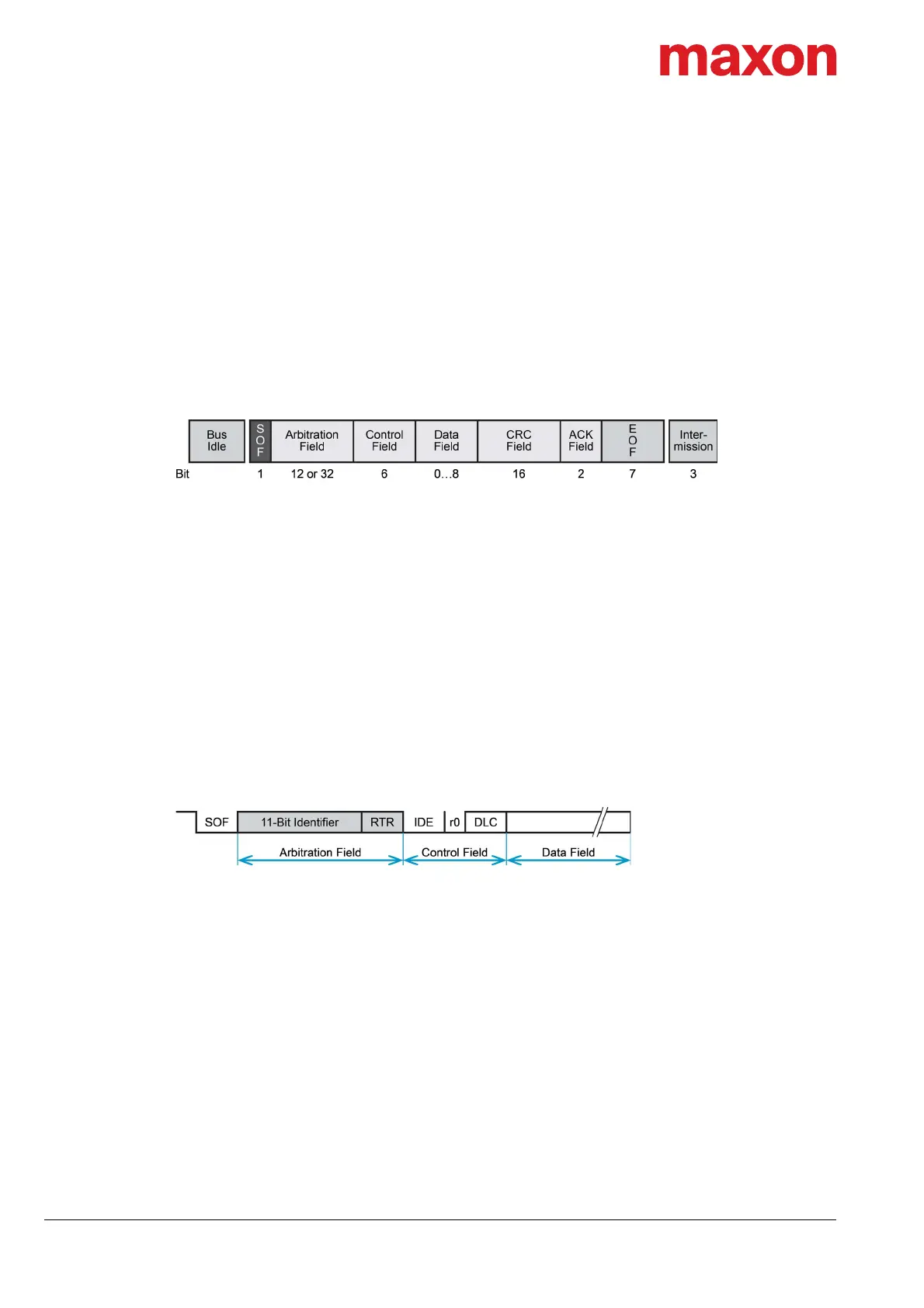
Figure 3-11 CAN communication – CAN data frame
• The Data Frame begins with a dominant Start of Frame (SOF) bit for hard synchronization of all
nodes.
• The SOF bit is followed by the Arbitration Field reflecting content and priority of the message.
• The next field – the Control Field – specifies mainly the number of bytes of data contained in the
message.
• The Cyclic Redundancy Check (CRC) field is used to detect possible transmission errors. It con-
sists of a 15-bit CRC sequence completed by the recessive CRC delimiter bit.
• During the Acknowledgment (ACK) field, the transmitting node sends out a recessive bit. Any node
that has received an error-free frame acknowledges the correct reception of the frame by returning
a dominant bit.
• The recessive bits of the End of Frame (EOF) terminate the Data Frame. Between two frames, a
recessive 3-bit Intermission field must be present.
With EPOS4, only the Standard Frame Format is supported.
Figure 3-12 CAN communication – Standard frame format
• The Identifier’s (COB-ID) length in the Standard Format is 11 bit.
• The Identifier is followed by the RTR (Remote Transmission Request) bit. In Data Frames, the RTR
bit must be dominant, within a Remote Frame, the RTR bit must be recessive.
• The Base ID is followed by the IDE (Identifier Extension) bit transmitted dominant in the Standard
Format (within the Control Field).
• The Control Field in Standard Format includes the Data Length Code (DLC), the IDE bit, which is
transmitted dominant and the reserved bit r0, also transmitted dominant.
• The reserved bits must be sent dominant, but receivers accept dominant and recessive bits in all
combinations.