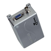
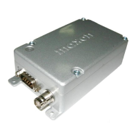
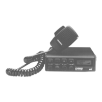
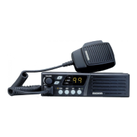
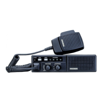
The SD-160 and SD-170 Series Data Radios, also referred to as "the radios," are RF wireless modems manufactured by MAXON, incorporating the latest technology in their design. These radios are controlled by a Phase Lock Loop Synthesizer (PLL) and a microprocessor, offering 16-channel capability. The SD-160 Series provides 2 watts of power, while the SD-170 Series offers a programmable output of 1 to 5 watts. Both UHF and VHF models are available.
Function Description:
The radios are designed for RF wireless data communication, functioning as modems. They support multiple baud rates from 1200 to 9600 and various modulation types including GMSK, FFSK, and FSK. The units feature programmable sub-audio squelch systems (CTCSS & DCS) and a two-tone squelch system, in addition to the standard signal level detect squelch system (RSSI). GPS Data handling is also provided to interface with and control an internal GPS receiver.
The radios are programmed using an IBM® Personal Computer with DOS® or WINDOWS®-based software, an interface module, and a programming cable. This allows for customization to meet specific user and system requirements.
Important Technical Specifications:
General:
- Equipment Type: Data radio (Wireless Modem)
- Model Series: SD-161 (VHF), SD-171 (VHF), SD-164 (UHF), SD-174 (UHF)
- Performance Specifications: TIA/EIA-603, ETS 300-113
- Frequency Range:
- VHF: 148-174MHz
- UHF: 450-490MHz
- RF Output:
- SD-161, SD-164: 2W Only
- SD-171, SD-174: 1-5W
- Channel Spacing: 12.5KHz, 25KHz Programmable
- Modulation Type: F3D, F3E
- Intermediate Frequency: 45.1MHz & 455KHz
- Number of Channels: 16
- Frequency Source: Synthesizer
- Operation Rating: Intermittent (90:5:5 Standby:RX:TX)
- Power Supply: Ext. Power Supply (12 VDC Nominal)
- Temperature Range:
- Storage: From -40°C to +80°C
- Operating: From -30°C to +60°C
- Current Consumption:
- Standby (Muted): < 65mA
- Transmit 5Watts RF Power: < 2.0 A
- Transmit 2Watts RF Power: < 1.0 A
- Lock Time: < 10ms
- TX to RX attack time: < 20ms (No Power Saving)
- RX to TX attack time: < 20ms
- Dimensions: (32mm)H X (58mm)W X (125mm)D
- Weight: 253 grams
Transmitter:
- Carrier Power (Nom. Max. Min.):
- SD-161, SD-164 (Hi Power): 2W < 3W > 1.5W
- SD-171, SD-174 (Hi Power): 5W < 6W > 4.5W
- SD-171, SD-174 (Low Power): 1W < 1.5W > 0.8W
- Sustained Transmission (Time: 5, 10, 30Sec): >90%, >85%, >80% (Nominal Conditions)
- Frequency Error:
- Nominal condition: < 0.5 KHz (VHF), < 0.75 KHz (UHF)
- Extreme condition: ±5.0 ppm
- Frequency Deviation:
- 25 KHz Channel Spacing: Peak ±5.0, Min. ±3.8
- 12.5 KHz Channel Spacing: Peak ±2.5, Min. ±1.9
- Audio Frequency Response: Within +1/-3dB of 6dB octave (@ 300 Hz to 2.55 kHz for 12.5 kHz C.S., @ 300 Hz to 3.0 kHz for 25 kHz C.S.)
- Adjacent Channel Power:
- 25 KHz Channel Spacing: < 70 dBc @ Nominal Condition, < 65 dBc @ Extreme Condition
- 12.5 KHz Channel Spacing: < 60 dBc @ Nominal Condition, < 55 dBc @ Extreme Condition
- Conducted Spurious Emission: < -60 dBc (VHF), < -30 dBm (UHF)
- Modulation Sensitivity: 100mV RMS @ 60% Peak Dev.
- Hum & Noise: > 40 dB (without PSOPH), > 40 dB (with PSOPH)
- Modulation Symmetry: < 10% Peak Dev @ 1KHz input for nominal dev. + 20dB
- Load Stability: No osc at ≥ 10:1 VSWR all phase angles and suitable antenna; No destroy at ≥ 20:1 all phase angle
- Peak Deviation Range Adjustment @ 1 KHz, Nom Dev + 20dB:
- 25 KHz Channel Spacing: Min. 3.5, Max. 6.0
- 12.5 KHz Channel Spacing: Min. 1.5, Max. 4.0
Receiver:
- Sensitivity (@ 12dB SINAD): < 0.28uV (25 KHz), < 0.30uV (12.5 KHz) for all models.
- Sensitivity (1/100 Error Rate): < -113dBm (with ACC-513), < -110dBm (with ACC-514) for all models.
- Adjacent Channel Selectivity:
- 25 KHz Channel Spacing (Nom.): > 65 dB (SD-161, SD-164), > 70 dB (SD-171, SD-174)
- 25 KHz Channel Spacing (Extreme Condition): > 55 dB (SD-161, SD-164), > 60 dB (SD-171, SD-174)
- 12.5 KHz Channel Spacing (Nom.): > 55 dB (SD-161, SD-164), > 60 dB (SD-171, SD-174)
- 12.5 KHz Channel Spacing (Extreme Condition): > 45 dB (SD-161, SD-164), > 50 dB (SD-171, SD-174)
- Spurious Rejection (100KHz ~ 4GHz): > 60 dB (SD-161, SD-164), > 70 dB (SD-171, SD-174)
- Image / Half IF Rejection: > 60 dB (SD-161, SD-164), > 70 dB (SD-171, SD-174)
- Intermodulation Response Rejection:
- ±25 kHz/ 50 kHz: > 60 dB (SD-161, SD-164), > 70 dB (SD-171, SD-174)
- ±50 kHz/ 100 kHz: > 60 dB (SD-161, SD-164), > 70 dB (SD-171, SD-174)
- Conducted Spurious Emission: < -57 dBm (9 KHz - 1 GHz), < -47 dBm (1 GHz – 4 GHz)
- RX Spurious Emissions (Radiated): < -57 dBm (9 KHz - 1 GHz), < -47 dBm (1 GHz – 4 GHz)
- AF Distortion:
- Nominal condition: < 5% (SD-161, SD-164), < 3% (SD-171, SD-174)
- Extreme condition: < 10%
- RX Hum & Noise (only audio): < 40 dB (without PSOPH), < 40 dB (with PSOPH)
- Receiver Response Time: < 16 ms
- Squelch (factory pre-set): Open -113dBm, Close -116dBm
- Squelch Attack Time: < 20 ms (RSSI), < 40 ms (Analog) at Threshold; < 10 ms (RSSI), < 30 ms (Analog) at Threshold + 20dB
- Squelch Decay Time: 5 ms Min., 20ms Max.
- Antenna Socket Input Match: > 10 dB Return Loss
- Temperature Stability for L.O. Frequency: 1st < 5 ppm, 2nd < 15 ppm from -30° to + 60° C
- L.O. Frequency Aging Rate: ±2 ppm/ year
Reference Crystal:
- Frequency: 12.8MHz
- Holder Type: HC-18
- Temperature Characteristic: ±5.0 ppm from -30° C to +60° C
- Aging Rate: < 2 ppm/ year in 1st year, < 1 ppm/ year thereafter
Environmental:
- Temperature (deg C):
- Operating: -30° to +60° C Degradation Specified @ Extreme condition
- Storage: -40° to +80° C
- ESD: 20 KV
- Vibration: MIL STD 810 C Procedures I, II, V and IEC68 26
Usage Features:
- 16 Channels: The SD-160/170 Series radios can store up to 16 channels within the same band, selectable via an internal DIP switch or serial commands from an external control system.
- Channel Spacing: Programmable 12.5KHz or 25KHz channel spacing for each channel in both UHF and VHF bands, configured via PC programmer ACC-916.
- Output Power: SD-160 offers 2-Watts output. SD-170 models are programmable for high-power (5 Watts) or low-power (1 Watt) output per channel via the PC programmer.
- Channel Scan: Supports channel scanning via serial commands for audio applications. Channels can be selected for a scan list during programming. When a conversation is detected on a scanned channel, the radio stops, releases audio through DB-15 pin 9, and sends busy channel data via serial command. Transmission during scanning occurs on the received call's channel during a programmable scan delay time (typically 4-7 seconds). After the delay, scanning resumes, and transmission will occur on the selected priority channel (assigned by inner DIP switch).
- Scan Delete: Temporarily removes a channel from the scan list by inputting a serial command while scanning and stopped on the channel. The channel remains removed until the scan is closed or the radio's power is reset.
- CTCSS / DCS Scanning: Can be programmed to scan for sub-audio tones to block unwanted calls.
- Busy Channel Lockout: When enabled, disables the transmitter if the receiving channel is busy. This feature is dealer-programmable (on/off) and applies to all channels.
- Marked Idle: In conjunction with Busy Channel, allows the locked-out transmitter to operate as long as a valid RX tone is received. Dealer-programmable (on/off) and applicable to all channels.
- TX Time-out: Limits continuous transmission time, settable in 10-second increments from 10 to 990 seconds. Five seconds before expiration, a Time-out alert signal is released through DB-15 pin 9, and transmission ceases.
- Power Save: For external battery use, allows programming of receiver ON/OFF times to set the duration the receiver "sleeps."
- Tx Delay: Keeps TX active for 150 ms after transmission ends when using CTCSS tones, eliminating squelch tail. Dealer-programmable (on/off).
- Squelch Options: Includes programmable sub-audio squelch (CTCSS & DCS) and two-tone squelch systems. Sub-audio squelch is available for Audio and FFSK signals but not for FSK (FM direct modulation of data) and GMSK signals due to frequency confliction.
- External Modems (ACC-513 GMSK, ACC-514 FFSK): Optional modem boards improve data transmission efficiency and flexibility. They connect to a computerized controller via an RS-232 serial data interface (COM1, COM2, etc. for PCs) to their Slave MCU. Received data drives the FFSK or GMSK modulator for serial data transmission. They also provide FFSK or GMSK demodulation for received data, converting it to RS-232 level serial data for the controller. FFSK can be mixed with sub-audio tones.
- GPS Option Board (ACC-515): Supports GPS data handling, outputting industry-standard NMEA GPS sentences on the DB-15 connector every 1 second. Received position data can be reprocessed by user applications. Power save mode is available, and a backup voltage ensures warm start at wake-up.
Maintenance Features:
- General Repair: Any repair or adjustment should be performed by or under the supervision of a qualified radio service technician.
- Electrostatic Discharge (ESD) Precautions: Before disassembling and reassembling the radio, wear a conduction wrist strap to prevent damage to components from electrostatic discharge.
- Separating Upper and Bottom Cover: Involves unfastening four mounting screws on the bottom cover and slowly opening the upper cover after removing the RF cable from the ANT. connector.
- Removing & Replacing RF Board: Requires unscrewing four upholding screws from the RF board, removing the shield plate, unscrewing two mounting screws on the PA module shield can, and then replacing the RF board assembly.
- Removing & Replacing Digital Board: Involves unfastening two hexagonal screws from the DB-15 connector, loosening the mounting screw on the left side of the digital board, removing two wires between the power connector and digital board, pulling the digital board out of the bottom cover, and then replacing the digital board assembly.
- Surface Mount Component Replacement: Surface mount components should be replaced using a temperature-controlled soldering system (soldering iron or hot-air system, 700°F/371°C). Heat should only be applied to metalized terminals. CMOS ICs require static precautions (discharge oneself, use grounded soldering equipment).
- Removal: Grip with tweezers, alternately heat terminals until solder liquefies, gently remove. Excess solder may need to be removed with a vacuum tool or wick.
- Replacement: "Tin" one terminal of the new component and corresponding PCB pad. Place component, observing polarity. Simultaneously touch tinned terminal and pad with soldering iron, pressing gently. Solder all terminals, allowing cooling time. Remove all flux after cooling.
- Surface Mounted Integrated Circuit Replacement: Similar to chip components, with extreme care and static precautions. Hot-air soldering is recommended. If unavailable, pins can be clipped and removed individually.