22
Chapter 5 Operation Guide
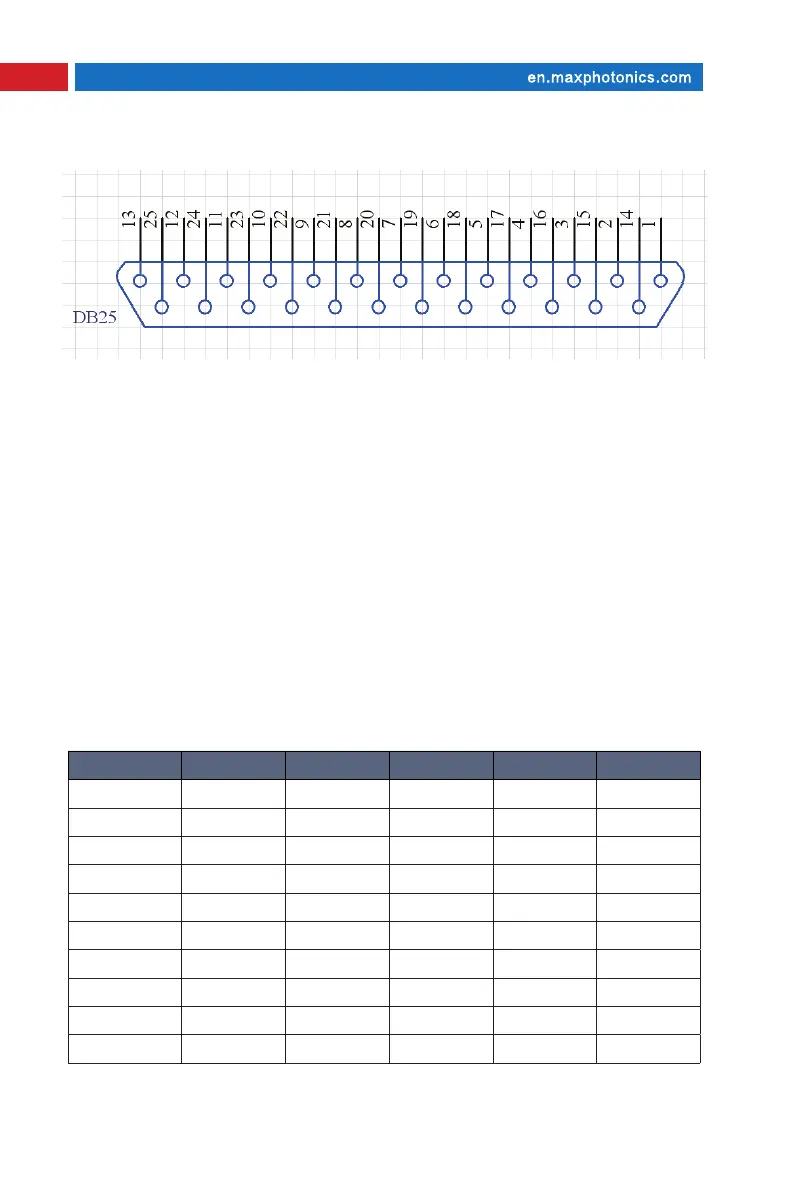
2. Digital Control Interface (DB-25) Description
(1)The laser is controlled via signals applied to the DB-25 connector.
Please refer to the connector interface description table above for 5.2.1
pin designation and operating levels.
(2)Pins 1 to 8 are the 8 bit bus for the output power setting. Pin 1 is the
least significant bit and pin 8 is the most significant bit. Codes in the range
0...255 (0...FFh) should be applied to these pins, which correspond to the
power setting of 0...100% of the specified nominal value, such as:
Set 1 Set 2 Set 3 Set 4 Set 5
Pin 1 0 0 0 0 0
Pin 2 0 0 0 0 0
Pin 3 0 0 0 0 0
Pin 4 0 0 0 0 0
Pin 5 0 0 0 1 1
Pin 6 0 0 1 1 1
Pin 7 0 1 1 1 1
Pin 8 1 1 1 1 1
Current 50% 75% 87.5% 93.75% 100%
Laser Power 35% 65% 85% 92% 100%