Do you have a question about the MAXPhotonics MFP-20 and is the answer not in the manual?
Information about safety symbols and their meanings.
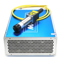
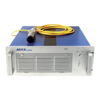
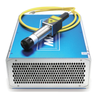
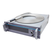
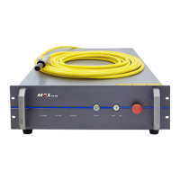
Details about the MFP-20 pulsed Ytterbium fiber laser.
List of included accessories with the laser device.
Guidelines for operating environment, power supply, and general safety.
Technical specifications including optical, electrical, and general characteristics.
Diagrams showing physical dimensions and mounting points for the laser unit.
Step-by-step instructions for installing the laser module and connecting components.
Detailed pinout and function for the 25-pin D-shape connector.
Explanation of control interface pins, power settings, and status indicators.
Procedures for starting, running the laser, and connecting power.
Pre-operation checks, system verification, and initial setup before running the laser.
Detailed steps for turning on the laser and performing initial tests.
Important warnings related to laser frequency, marking results, and direct power control.
Details on the standard warranty period and coverage for MAXPHOTONICS fiber lasers.
Exclusions and conditions that may void the product warranty.
Procedures for requesting service or repairs and contacting support.
Form and instructions for initiating a Return Material Authorization (RMA).
Detailed guidelines for returning products for warranty claims or repairs.
Procedures and responsibilities for returns not covered by warranty.
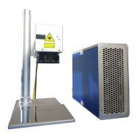
The MAXPHOTONICS MFP-20 is a Class IV pulsed Ytterbium fiber laser, designed as a high-performance OEM device for integration into high-speed, high-resolution laser marking systems. It offers significant improvements in per-Watt optical power efficiency, low power consumption, and a robust design compared to traditional diode-pumped solid-state lasers. The MFP-20 is suitable for both laboratory and field operations, featuring a compact, rugged, stand-alone, ready-to-use, turn-key design that can be directly integrated into a user's apparatus.
The MFP-20 laser emits a periodical pulse train at a wavelength of 1064 nm, with a peak power of up to 20 KW. The pulse repetition rate can be controlled either via a separate remote control unit or by an external PC. The device requires a 24V external DC power supply. It is designed for laser marking applications, offering precise control over output power and pulse characteristics.
The MFP-20 is controlled via a DB25 interface. Pins 1-8 are used for setting the output power (8-bit, 0-255, corresponding to 0-100% standard power data). Pin 9 is a latch for simultaneous power setting. Pins 10-15 and 24 are ground. Pins 16 and 21 indicate laser alarm status (e.g., laser temperature out of range, normal operation, high optical "Back Reflection" leading to automatic shutdown, MO failure). Pin 17 provides a 5±0.25VDC auxiliary power supply for independent guide laser operation. Pin 18 controls the Master Oscillator (MO) ON/OFF. Pin 19 is the Laser Modulation input (Power Amplifier ON/OFF). Pin 20 is for Pulse Repetition Rate (Synchronization) input, accepting TTL/CMOS square waves with a duty cycle from 0.1 to 0.9. Pin 22 controls the Guide Laser (red diode) ON/OFF. Pin 23 is the Emergency Stop Input, where a LOW signal automatically switches off the laser.
The device is designed for minimal user maintenance. No operator-serviceable parts are inside. All servicing and maintenance are performed at the factory by qualified MAXPHOTONICS personnel. Opening the device or any tampering will void the warranty. It is crucial to keep the output lens clean. After use, the collimator should be recovered.
The warranty for Maxphotonics fiber lasers is 24 months from the customer's receipt date. MAXPHOTONICS warrants products against defects in materials and workmanship under normal use. Repairs or replacements are at MAXPHOTONICS' option. Warranty is voided by tampering, misuse, neglect, accident, use outside specifications, or improper installation/maintenance. Fiber connectors are not covered by the warranty. Returns require a Return Material Authorization (RMA) number from MAXPHOTONICS Quality Manager. Defective products must be returned freight prepaid and insured. Non-warranty returns and international returns may incur freight costs, duties, and taxes. All returns must be adequately packaged to prevent damage.
| Brand | MAXPhotonics |
|---|---|
| Model | MFP-20 |
| Category | Measuring Instruments |
| Language | English |