MAXPHOTONICS CO.,LTD
WWW.MAXPHOTONICS.COM
12
Control Interface Operation as followings
1.This laser is controlled by connecting through the DB25 interface, the detail
information please view above sheet
2. Pin1~8 are the main line of setting the power of 8 bit,Pin1 is LSB,Pin8 is MSB。
The input range of this Pin
is 0~255,and with 0~100% standard power data.
e.g.: please see as following sheet
Setup1 Setup 2 Setup 3 Setup 4 Setup 5
Pin1 0 0 0 0 1
Pin2 0 0 0 0 1
Pin3 0 0 0 0 1
Pin4 0 0 0 0 1
Pin5 0 0 0 1 1
Pin6 0 0 1 1 1
Pin7 0 1 1 1 1
Pin8 1 1 1 1 1
Current 50% 75% 87.5% 93.75% 100%
The power of
the laser
35% 65% 85% 92% 100%
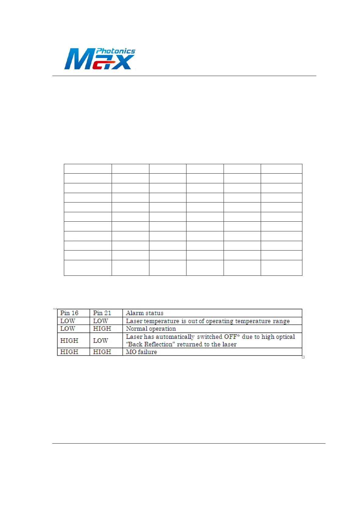
4. Pin16 and Pin21 are for warning, the 2 Pin show the situation as followings.
5. Pin18 is the switch sign of MO(main surge).MO should be turn on before 4ms when
open the Booster(BS).After turning on the MO ,the laser will have some electricity
consumption.
Notes:MO and Pin18 should be turning on at the same time.
6.
Pin19 is the input end of launching controller Booster(BS).when level is H, please
turn on the BS, when level is L, please turn off BS, when the Pin19 change to lever