MAXPHOTONICS CO.,LTD
WWW.MAXPHOTONICS.COM
13
H, the laser will be out after stated delay. When the level is L, the laser will be turned
off after stated delay.
Notes:
a.
MO should be turned on before 4ms of BS, if not, it will be no laser output.
b. If turning on the BS first, then the MO,the laser will be out after 1~4ms. The
above two situation is not list in the manual as they are unusual operation, please try
to avoid them. BS should be turned on together with the data rising.
7. Pin20 is the input interface of in-phase,The pulse of laser output should be the same
steps with signal rising at the stated range ,the pulse repetition rate from this side to input
(PRR)(referring the limitation of PRR)
.
Notes:if the input PRR above the stated range, the protection system of laser will
protect the loop and recruit the loss pulse or limitation the data of PRR
.
8.
Pin23 is the input interface of “emergency stop”. When running ok, the level should
be H, once the level change to L, the laser will be stopped automatically( the same with
MO&BS)which isn’t depend on the other control signal. When restart the laser, please
make sure that the level of MO &BS should be down to L (if the original is H).If need
the laser running normally, this signal should be at H level 2μs earlier before offering the
MO&BS.
Laser Running
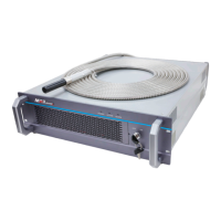
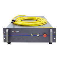
1.Please take off the protecting covering from the laser output head.
2.Please connected the laser mold and control system through DB-25 interface, please
make reference from the leading of DB25 if necessary
3.Please make sure that the following interface at the initialization rightly
a) Pin18,19,22,23 at level L ;
b) The Repetition frequency of Pin20 at the stated range
4. C
onnected the 24VDC power and laser power line(+24V to brown,ground to
green/yellow,- to blue)
5. Laser will be running after 120s when gaining the 24VDC power(warming-up time).
Notes:it’s allowing to offer the 24VDC main power first,then make the control
signal initial
6. Make the emergency stop to(Pin23)H。
7. Set up the required power through Pin1~8.