23
Chapter 5 Operation Guide
Set 1 Set 2 Set 3 Set 4 Set 5
Pin 1 0 0 0 0 0
Pin 2 0 0 0 0 0
Pin 3 0 0 0 0 0
Pin 4 0 0 0 0 0
Pin 5 0 0 0 1 1
Pin 6 0 0 1 1 1
Pin 7 0 1 1 1 1
Pin 8 1 1 1 1 1
Current 50% 75% 87.5% 93.75% 100%
Laser Power 35% 65% 85% 92% 100%
(
3
)
Pins 16 and 21 are the alarm and status outputs. These pins indicate the
following device states:
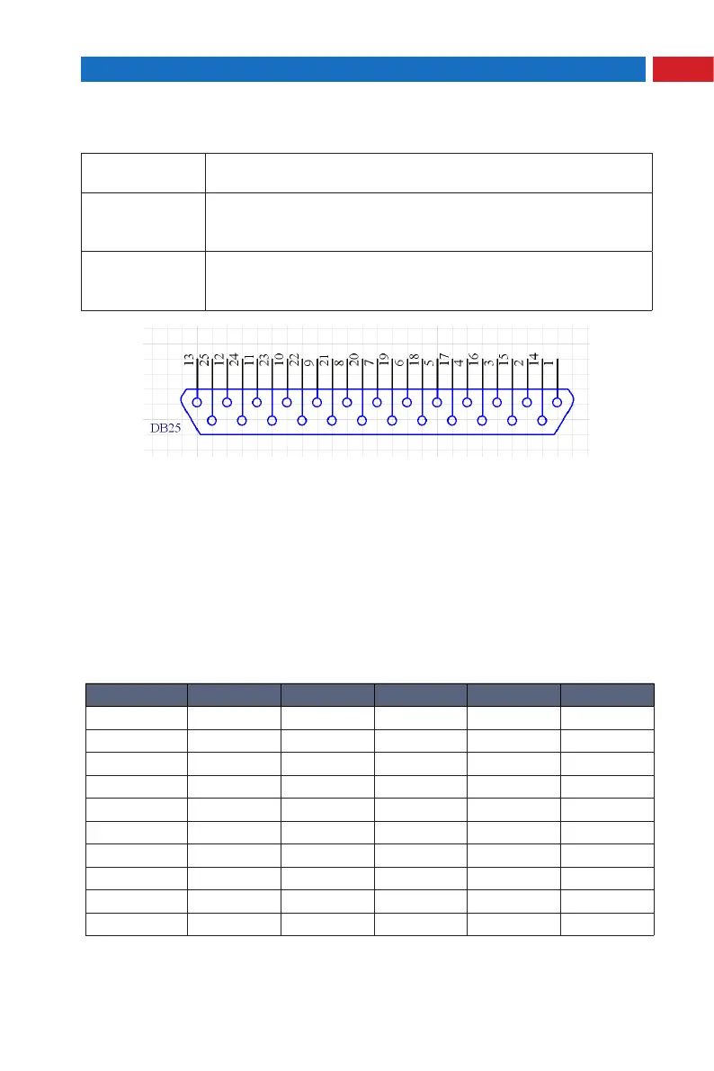
2. Digital Control Interface (DB-25) Description
(
1
)
The laser is controlled via signals applied to the DB-25 connector. Please
refer to the connector interface description table above for 5.2.1 pin designation
and operating levels.
(
2
)
Pins 1 to 8 are the 8 bit bus for the output power setting. Pin 1 is the least
signicant bit and pin 8 is the most signicant bit. Codes in the range 0...255
(0...FFh) should be applied to these pins, which correspond to the power setting
of 0...100% of the specied nominal value, such as:
20
Pulse Repetition Rate (Synchronization) input
Refer to PRR range. Allowed duty cycle is 0.1~0.9.
22
Guide Laser (red diode) ON/OFF input
- HIGH: ON
- LOW or disconnected
:
OFF
23
Emergency Stop Input
- High: OK (Normal operation)
- LOW or disconnected: STOP