29
Chapter 6 Operation Guide
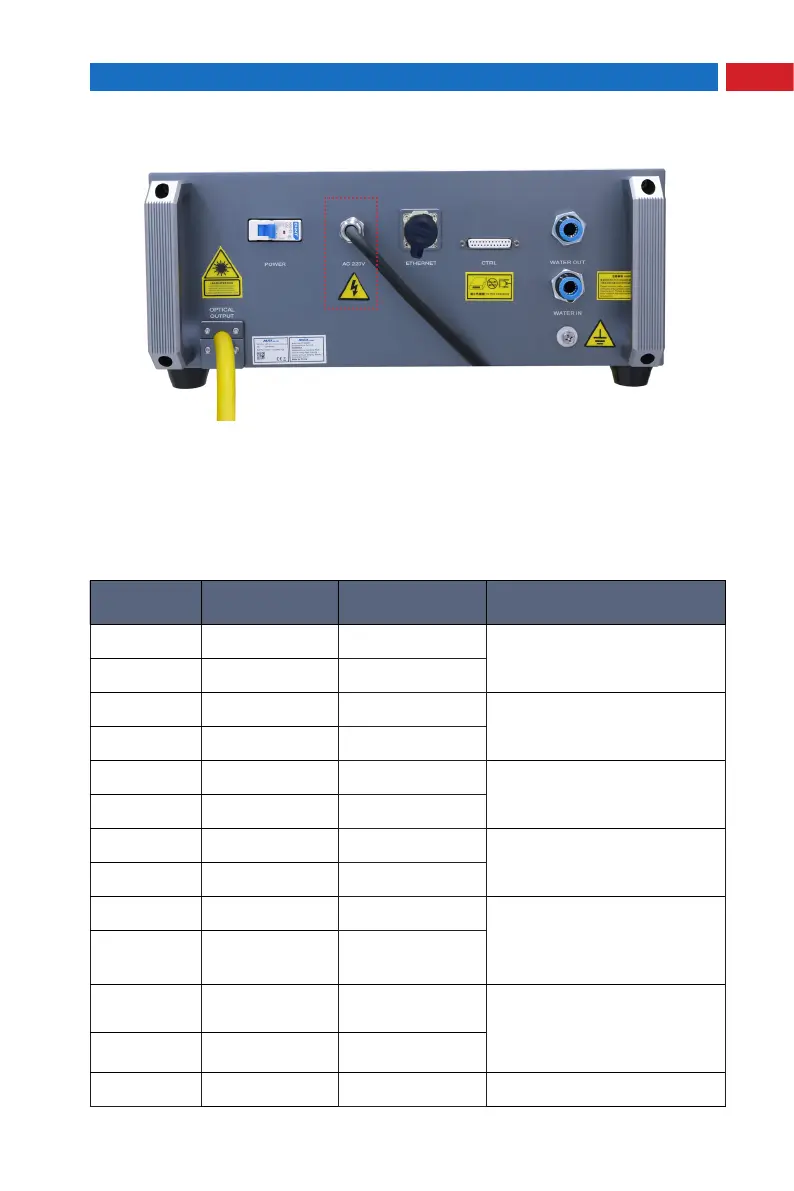
3- Extension Interface
The laser CTRL interface is a high quality DB25 interface that provides a variety
of signals for the functional control of the laser, as described below:
CTRL Interface Definition
Ctrl
Interface Pin
Wire Color
Function
Description
Notes
18 Red Enable input +
HIGH:20VDC ≤ V ≤24VDC
LOW:0VDC ≤ V ≤ 5VDC
5mA ≤ I ≤15mA
5 Red And White Enable input -
17 Black Modulation input +
HIGH:20VDC ≤ V ≤24VDC
LOW:0VDC ≤ V ≤ 5VDC
5mA ≤ I ≤15mA
4 Black And White Modulation input -
16 Yellow External light +
HIGH:20VDC ≤ V ≤24VDC
LOW:0VDC ≤ V ≤ 5VDC
5mA ≤ I ≤15mA
3 Yellow Black External light -
15 Green DA (0-10V) input +
Control laser output power
(
1V-10%
,
10V-100%
)
2 Green And White DA (0-10V) input -
14 Brown Fault output 1
Dry contact output, ON- fault,
OFF- normal, (contact voltage
V ≤ 30VDC, contact current I ≤
100mA)
1 Brown And White Fault output 2
19 Blue Interlock+
±Short connection: the laser
normally controls the light
±Disconnected: the laser is
locked and cannot emit light
6 Blue And White Interlock-
Ground wire Green Yellow Ground wire
 Loading...