XStream™OEMRFModule–ProductManualv5.x00[2006.02.24]
1.4. Pin Signals
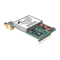
Figure1‐02. XStreamOEMRFModulePinNumbers(bottomview,pinsprotruding)
Table1‐02. J1PinSignalDescriptions
(Low‐assertedsignalsdistinguishedwithahorizontallineoversignalname.)
Module Pin Signal Name I/O When Active
Function
(clear-to-send) flow control – When pin is driven low,
UART host is permitted to send serial data to the module.
Refer to the Serial Communications [p
9] and CS Command
[p
23] sections for more information.
1
DO2 /
/
RS-485 Enable
O* low
RS-485 Enable – To configure this pin to enable RS-485
(2-wire or 4--wire) communications, refer to the Serial
Communications [p
9] and CS Command [p23] sections.
2 DI3 / SLEEP I* high
By default, DI3 pin is not used. To configure this pin to support
Sleep Modes, refer to the Sleep Mode [p
13], SM Command
[p
32] and PW Command [p29] sections.
3 DO (data out) O* n/a
Serial data exiting the module (to the UART host). Refer to the
Serial Communications [p
9] section for more information.
4 DI (data in) I n/a
Serial data entering the module (from UART host). Refer to the
Serial Communications [p
9] section for more information.
(request-to-send) flow control – By default, this pin is not
used. To configure this pin to regulate the flow of serial data
exiting the module, refer to the Serial Communications [p
9] and
RT Command [p
31] sections.
5 DI2 / / CMD I** low
CMD –Refer to Binary Commands [p
17] and RT Command
[p
31] sections to enable binary command programming.
6 I* low Re-boot module.
7 DO3 / RX LED O high
Pin is driven high during RF data reception; otherwise, the pin
is driven low. Refer to the CD Command [p
22] to enable.
low - Pin pulses low during RF transmission.
8 / PWR O
high PWR – Indicates power is on and module is not in Sleep Mode.
9 I*** low
Pin can be used as a backup method for entering Command
Mode during power-up. Primary method is with “+++”. Refer to
the Command Mode [p
16] section for more information.
10 VCC I - 5 VDC regulated (± 0.25)
11 GND - - Ground
* Modulehas10KΩinternalpull‐upresistor
** Modulehas10KΩinternalpull‐downresistor
*** Modulehas100KΩinternalpull‐upresistor
Note: When integrating the XStream Module with a Host PC Board, all lines that are not used should
be left disconnected (floating).
Table1‐03. J2PinSignalDescriptions
Module Pin Signal Name
1 reserved
2 GND
3 GND
4 GND
J2Pinsareusedprimarilyformechanicalstabilityandmaybeleftdisconnected.
©2006MaxStream,Inc.ConfidentialandProprietary 6
Downloaded from Elcodis.com electronic components distributor
 Loading...