L
4
L
h
1
K
2
Ø b
Ø D
1 h9
*
c
2
Ø G
2
H8
g
c
2
Ø b
Ø Z
Ø s
1
z
t
Ø D
g7
Ø G
1
H7
Ø D
2
Ø M
1
L
5
L
2
h
1
K
3
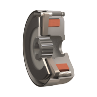
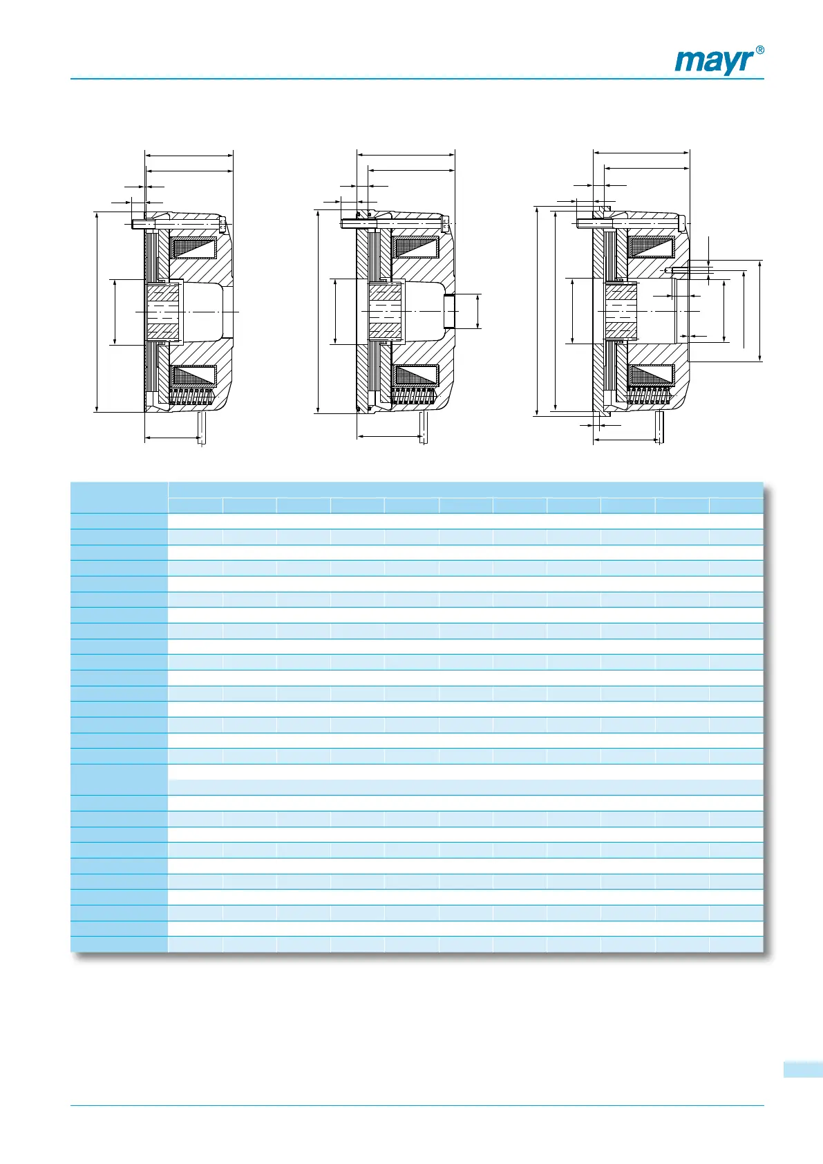
ROBA-stop
®
-M electromagnetic safety brakes
Type 891._12.0
Standard with friction disk
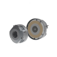
Type 891._14.1
Enclosed design (IP 65)
with flange plate
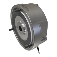
Type 891._14.2
Tacho attachment design
with flange plate
1) Braking torque tolerance = +30 %/-10 %, for other adjustments see
Table 3, page 7 and Type key page 3.
1.1) Minimum bore not permitted for braking torque adjustment = 125 %.
1.2) Braking torque tolerance = +40 %/-20 % (slight grinding necessary).
2) The respective maximum bores are to be seen in relation to the
corresponding keyways and their tolerances acc. Table 2 page 7.
3) Brake operation from 700 Nm on only possible with overexcitation.
4) Hub facing side (both sides) 3 mm deep, Ø 97 recessed.
5) Brake operation only possible with overexcitation.
6) The IP65 design is equipped with a sealing cover on size 1000:
L = 149 mm, L
4
= 170 mm.
7) Projection screw plugs (emergency hand release): 8,5 mm
8) For flange plate securement: additional 2 x M12 screws (dimensions
available on request).
Standard voltages 24; 104; 180; 207 V. We reserve the right to make dimensional and constructional alterations.
Permitted voltage tolerance acc. DIN IEC 60038 (±10 %).
* Outer diameter friction disk: free size; outer diameter flange plate: -0,2 Missing dimensions are identical with Type 891.011.0 see page 4.
Dimensions
[mm]
Size
2 4 8 16 32 60 100 150 250 500 1000
G 16,5 18 22 33 36 38 48 55 65 85 100
G
1
23,5 28,5 32,5 40,5 52,5 60 75,5 82,5 92 131 100
G
2
H8
- - 22 22 28 32 42 48 52 62 100
g 4 4 4 4 4 4 5 6 7 7 7
H 16 14,5 17,5 26 27 26 34 41 46 54,5 -
h 1 1 1 1,25 1,25 1,25 - - - - -
h
1
5 6 6 7 8 8 10 12 14 19 21
K 10 10,8 12,5 12,3 8,3 12 12 20 20 22 18,5
K
1
9 9,8 11,5 11,1 7,1 10,8 - - - - -
K
2
10 8,8 11,5 10,3 10,3 14 12 18 25,5 21,5 17,5
K
3
10 9,8 11,5 10,3 10,3 14 12 18 26 23 19
L 39 41,5 45,2 55,7 61,7 72,5 84 97 116 114 135
6) 7)
L
2
38 40,5 44,2 54,7 60,7 71,5 83 96 115 113 135
7)
L
3
40 42,5 46,2 57 63 73,8 - - - - -
L
4
44 47,5 51,2 62,7 69,7 80,5 94 109 130 133 170
6)
L
5
43 46,5 50,2 61,7 68,7 79,5 93 108 129 132 156
7)
l
18 18 20 20 25 30 30 35 40 50
4)
70
supporting length of the key
M 66 72 90 112 132 145 170 196 230 278 325
M
1
29 35 41 52 61 75 88 100 112 145 115,5
R 57 65 81 101 121 130,5 154 178 206 253 300
r 45 45 53 70 83 94 106 122 140 161 190
s 3 x M4 3 x M4 3 x M5 3 x M6 3 x M6 3 x M8 3 x M8 3 x M8 3 x M10 6 x M10 6 x M12
8)
s
1
3 x M3 3 x M4 3 x M4 3 x M4 3 x M5 3 x M5 3 x M5 3 x M6 3 x M6 6 x M8 6 x M6
t 6 10 10 10 10 10 10 10 10 13 12
x 0 0 0 0 - 0,5 0 - 0,5 0 - 2 0 - 3 0 - 3 0 - 3 3 - 4 0 – 1,5
Z 36 45 55 65 75 90 100 115 130 175 -
z 1 1 1 1 1 1 1 1 1 1 -
55