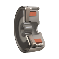
ROBA-stop
®
-M – Short Description Installation
Technical Data for Installation
Size
2 4 8 16 32 60 100 150 250 500 1000
Inspection dimension
[mm] 0,9
+0,1
0,9
+0,1
1,1
+0,1
1,6
+0,1
1,8
+0,1
2,2
+0,1
2,2
+0,1
2,2
+0,1
2,4
+0,1
2,4
+0,1
-
Number of rotations
Y
[-] 1,7 1,7 1,5 2,0 2,0 2,0 1,6 1,6 1,5 1,5 -
Release force
Standard brake
Type 891.
0
_ _._
2
F
[N] 20 35 70 100 130 220 260 290 350 310 -
Holding brake
Type 891.10 _._
F
[N] 26 45 90 125 170 300 340 350 430 470 -
Release angle
a
[°] 6 7 7 7 8 10 12 13 10 10 -
Fixing
screws (8)
Type 891._
_0._
[-]
3 x
M4 x
45
3 x
M4 x
45
3 x
M5 x
50
3 x
M6 x
60
3 x
M6 x
60
3 x
M8 x
75
3 x
M8 x
80
3 x
M8 x
100
3 x
M10 x
110
6 x
M10 x
110
6 x
M12 x
130
DIN 6912 6912 6912 6912 6912 6912
EN ISO
4762
EN ISO
4762
EN ISO
4762
EN ISO
4762
EN ISO
4762
Type 891._ _4._
[-]
3 x
M4 x
50
3 x
M4 x
50
3 x
M5 x
55
3 x
M6 x
65
3 x
M6 x
70
3 x
M8 x
85
3 x
M8 x
90
3 x
M8 x
110
3 x
M10 x
130
6 x
M10 x
130
6 x
M12 x
150
DIN
EN ISO
4762
EN ISO
4762
6912 6912
EN ISO
4762
EN ISO
4762
EN ISO
4762
EN ISO
4762
EN ISO
4762
EN ISO
4762
EN ISO
4762
Tightening torque for screws (8)
T
A
[Nm] 2,5 2,5 5,0 9,0 9,0 22 22 22 45 45 83
Rotor thickness “new condition“ [mm] 6,05 6,05 6,9 8 10,4 11,15 14 15,5 17 18,5 18,5
Table 1
Permitted Bores Ø d
max
Size
2 4 8 16 32 60 100 150 250 500 1000
Ø d
max
Type 891.
0
_ _._
2
Keyway
JS9
6885/1 13 13 18 22 30 32 42 45 55 75 90
6885/3 15 15 20 25 - 35 45 50 60 80 -
Keyway
P9
6885/1 13 13 18 20 28 32 42 45 50 75 90
6885/3 15 15 20 22 30 - 45 50 55 80 -
Type 891.1_ _._
Keyway
JS9
6885/1 13 13 18 22 30 32 42 45 55 75 90
6885/3 15 15 20 25 - 35 45 50 - - -
Keyway
P9
6885/1 13 13 18 20 28 32 42 45 50 75 90
6885/3 15 15 20 22 30 - 45 50 55 - -
Table 2
Braking Torque Adjustments
Size
2 4 8 16 32 60 100 150 250 500 1000
3)
Holding brake [Nm] 4 8 16 32 64 100 180 250 450 800
2)
1600
Standard brake
Braking torque
4)
in %
125 % [Nm] 2,5 5 10 20 40 75 125 185 312 700
1)
1400
112 %
[Nm] 2,2 4,5 9 18 36 68 110 165 280 560 1200
100 % [Nm] 2 4 8 16 32 60 100 150 250 500 1000
84 % [Nm] 1,7 3,4 6,8 13,5 27 51 85 125 215 400 800
68 % [Nm] 1,4 2,8 5,5 11 22 42 70 100 180 350 700
50 % [Nm] 1 2 4 8 16 30 50 75 125 250 500
34 % [Nm] 0,7 1,4 2,8 5,5 11 21 35 50 90 200 400
Table 3
1) Brake operation only as holding brake.
2) Brake operation from 700 Nm only possible with overexcitation.
3) Brake operation only possible with overexcitation.
4) The braking torque (switching torque) is the torque effective in the shaft train of a slipping brake with a sliding speed of 1 m/s in relation to the mean friction
radius (acc. VDE 0580/07.2000).
77