240 EdwargsStreeL SE
Cleveland,Tennessee37311
Tel:423-472-3333
Fax:423-478-6710
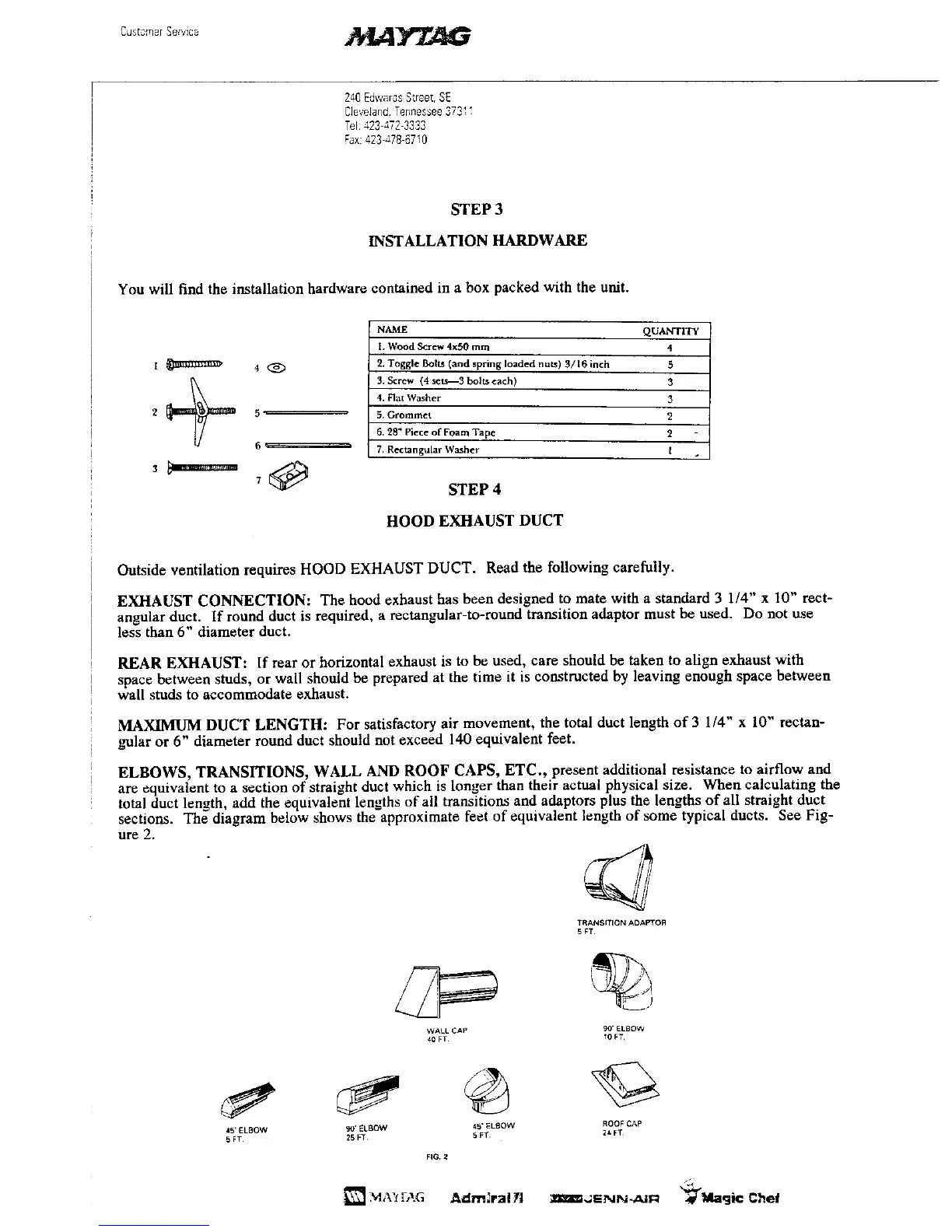
STEP 3
INSTALLATION HARDWARE
You will find the installation hardware contained in a box packed with the unit.
NAME QUANTITY
I. Wood S_rew 4x50 mm 4
I _ .............. P 4 @ 2. Toggle Bolts (and spring loaded nuts) 3/16 inch 5
3. Screw {4set_-3 bolts each) 3
4. Rat Washer 3
2 5 -- 5. Grommet 2
6. 28" Piece of Foam Tape 2
6 '_ ' 7. Rectangular Washer I .
3
7 _ STEP 4
HOOD EXHAUST DUCT
Outside ventilation requires HOOD EXHAUST DUCT. Read the following carefully.
EXHAUST CONNECTION: The hood exhaust has been designed to mate with a standard 3 1/4" x 10" rect-
angular duct. If round duct is required, a rectangular-to-round transition adaptor must be used. Do not use
less than 6" diameter duct.
REAR EXHAUST: If rear or horizontal exhaust is to be used, care should be taken to align exhaust with
space between studs, or wall should be prepared at the time it is constructed by leaving enough space between
wall studs to accommodate exhaust.
MAXIMUM DUCT LENGTH: For satisfactory air movement, the total duct length of 3 1/4" x 10" rectan-
gular or 6" diameter round duct should not exceed 140 equivalent feet.
ELBOWS, TRANSITIONS, WALL AND ROOF CAPS, ETC., present additional resistance to airflow and
are equivalent to a section of straight duct which is longer than their actual physical size. When calculating the
total duct length, add the equivalent lengths of all transitions and adaptors plus the lengths of all straight duct
sections. The diagram below shows the approximate feet of equivalent length of some typical ducts. See Fig-
ure 2.
TRANSITION ADAI_f OR
5 FT
WALL CAP 9O"ELBOW
40 FT _0 FT
45"ELBOW _" ELBOW 45"ELBOW ROOFCAP
5FT 25FT 5FT 2_FT
FIG.2
_'_4A'frAG Adm3rallCl _m_',_SNN_=J. "_Magic Chef
 Loading...