Component Testing Procedures
!
WARNING
To avoid risk of electrical shock, personal injury or death; disconnect power to washer before servicing, unless
testing requires power.
16022846 Rev 0 December 2003
2
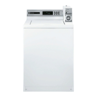
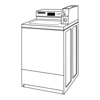
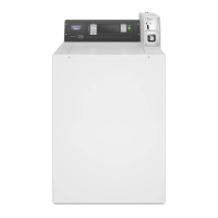
Illustration Component Test Procedure Results
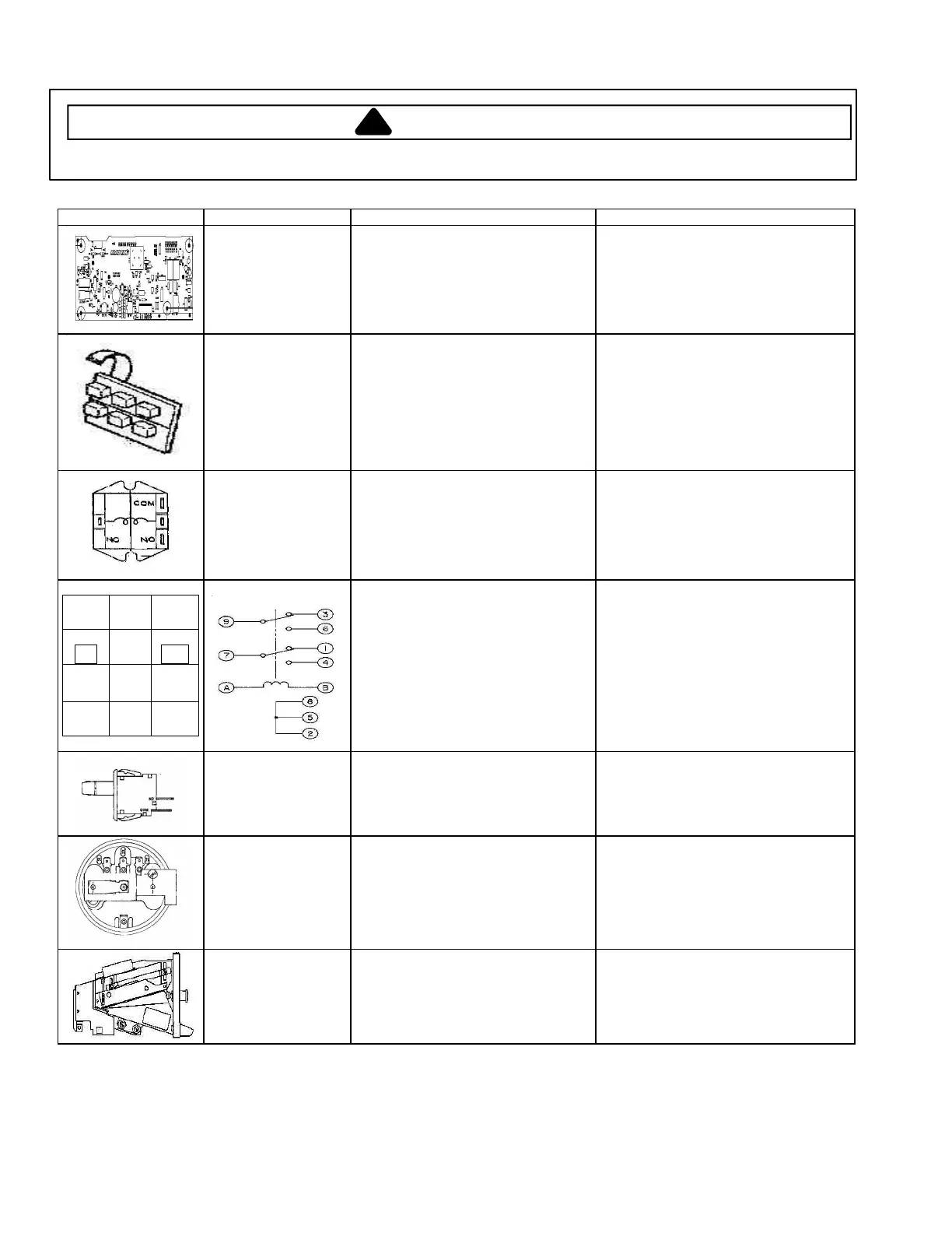
Control Board Proper grounding is necessary when
handling microprocessor board to
prevent damage from static electricity.
See Control Board Connections
Section.
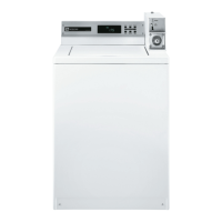
Touch Pad
Depress the proper button, checking
for continuity.
Whites
Colors
Bright colors
Permanent Press
Wool
Delicate & Knits
Continuity, if not replace.
1 to 3
1 to 2
1 to 4
5 to 3
5 to 2
5 to 4
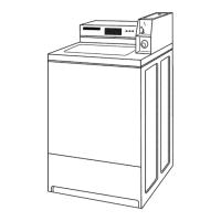
Motor Relay Relay Coil: Grey to Orange/Black ------
Switch Terminals: Common to N.O.----
Relay Coil Energized-----------------------
Approx 350 – 450 Ω
Internal switch circuit is open. If switch
is welded closed, replace switch.
24VDC. Check for signal from control
board if not present.
1
WH
2
L2
3
RD
4
RD
5
RD
6
WH
7
YL
8
BR
9
BU
A
PU
B
GY
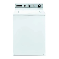
Reversing Relay
Relay coil: Purple and Gray (A to B)----
Terminals and Wires:
Agitate (1) White to (7) Yellow----------
(3) Red to (9) Blue---------------
(7) Yellow to (4) Red-------------
(9) Blue to (6) White-------------
Approximately 350 – 450 Ω
Closed circuit
Closed circuit
Open circuit
Open circuit
Vault and Service
Switch
Disconnect wire terminals from switch.
Check for continuity between
terminals: Common to N.O.
Circuit is open until switch plunger is
depressed. If not, replace switch.
Pressure Switch Disconnect wire terminals from switch.
Measure resistance across the
following terminals:
Empty (Filling) 20 to 15--------------------
Full (Run) 20 to 15 -------------------------
Resistance above 2 Ω indicates dirty
switch contacts.
Closed circuit
Open circuit
Coin Drop Check for coin Movement.
Diameter of Coin----------------------------
Thickness of Coin---------------------------
Rear of Chute (Penny Window)----------
Restricted: Clean and adjust if
necessary.
Adjust guide rail if necessary.
Examine Pinch adjustment.
Bend two deflector scoops if necessary.