Component Testing Procedures
!
WARNING
To avoid risk of electrical shock, personal injury or death; disconnect power to washer before servicing, unless
testing requires power.
December 2003 16022846 Rev 0
3
Illustration Component Test Procedure Results
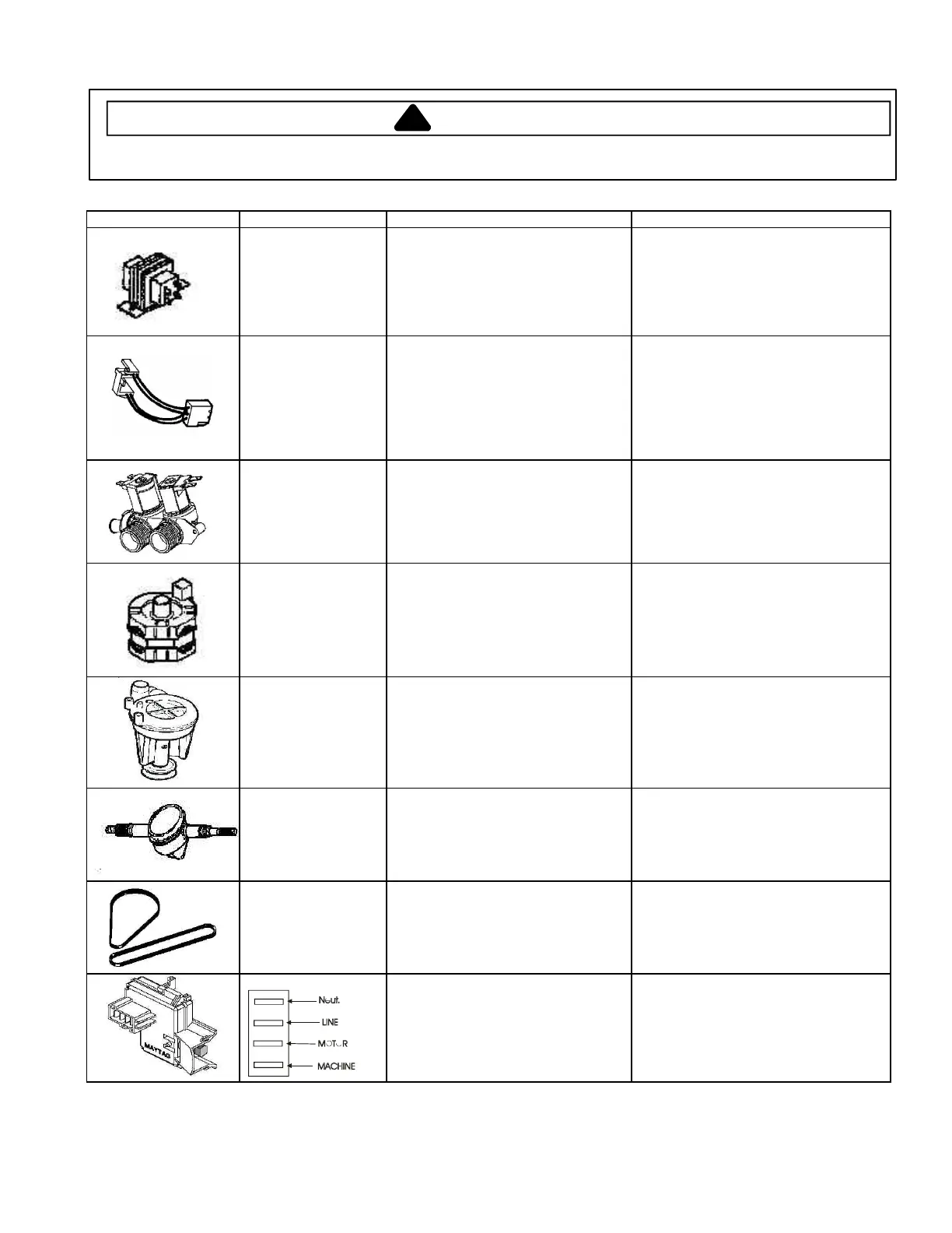
Step-Down
Transformer
Check voltage.
Primary Side:---------------------------------
Secondary Side:
AA6-1 to AA6-2------------------------------
AA6-1to AA6-5 -----------------------------
AA6-2 to AA6-5-----------------------------
AA6-3 to AA6-6------------------------------
120 VAC
2.65 VAC
2.65 VAC
5.3 VAC
22.5 VAC
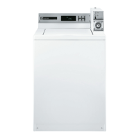
Coin sensor Check for coin registering.
Coin Sensor Voltage Checks:
1) Blocked- White to Red-----------------
2) Unblocked- White to Red--------------
3) Continuously- Blue to White /Blue---
Display flashes an “*” in “Service Mode”.
23 VDC
0.6 VDC
1.5VDC Note: Replace sensor if voltage
is 23VDC (Open Diode),or 0 VDC
(Shorted Diode),
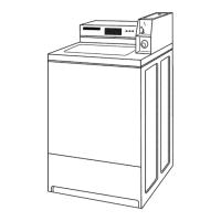
Water Valve Measure resistance across the
terminals of each coil on the valve.
Measure resistance across thermistor
terminals water temperature (60°F -
140°F degrees).
Approximately 850-950 Ω
Approximately 10K-85KΩ
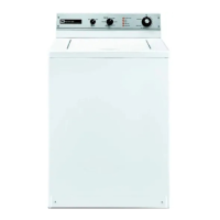
Motor Type of Motor:
Single speed (Split phase)
See “Motor Testing” section for
correct wiring contact.
Pump Verify drain pump is not clogged or
damaged.
1) Remove clog and verify proper
operation.
2) Replace drain pump if damaged.
Transmission Type of transmission (orbital):
618 r.p.m. Spin
150 o.p.m. Agitate
Check wattage with full tub of water
only (Use Wattage Meter).
See section on “Transmission”
disassembly procedures in base
manual.
380 to 420 watts
Belts Check belt for excessive wear or being
burnt and cracking.
Replace if belt if damaged.
Lid Switch (series 15)
Check for Continuity between the
following terminals:
Line to Machine (Lid Open) --------------
Line to Motor (Lid Closed)----------------
Line to Machine (Lid open or Closed)--
Closed Circuit
Closed Circuit
Closed Circuit, If not replace lid switch.