Component Testing Information
!
WARNING
To avoid risk of electrical shock, personal injury or death, disconnect power to unit before servicing, unless testing
requires power.
14 16025911 Rev. 0 ©2005 Maytag Services
Illustration Component Test Procedure Results
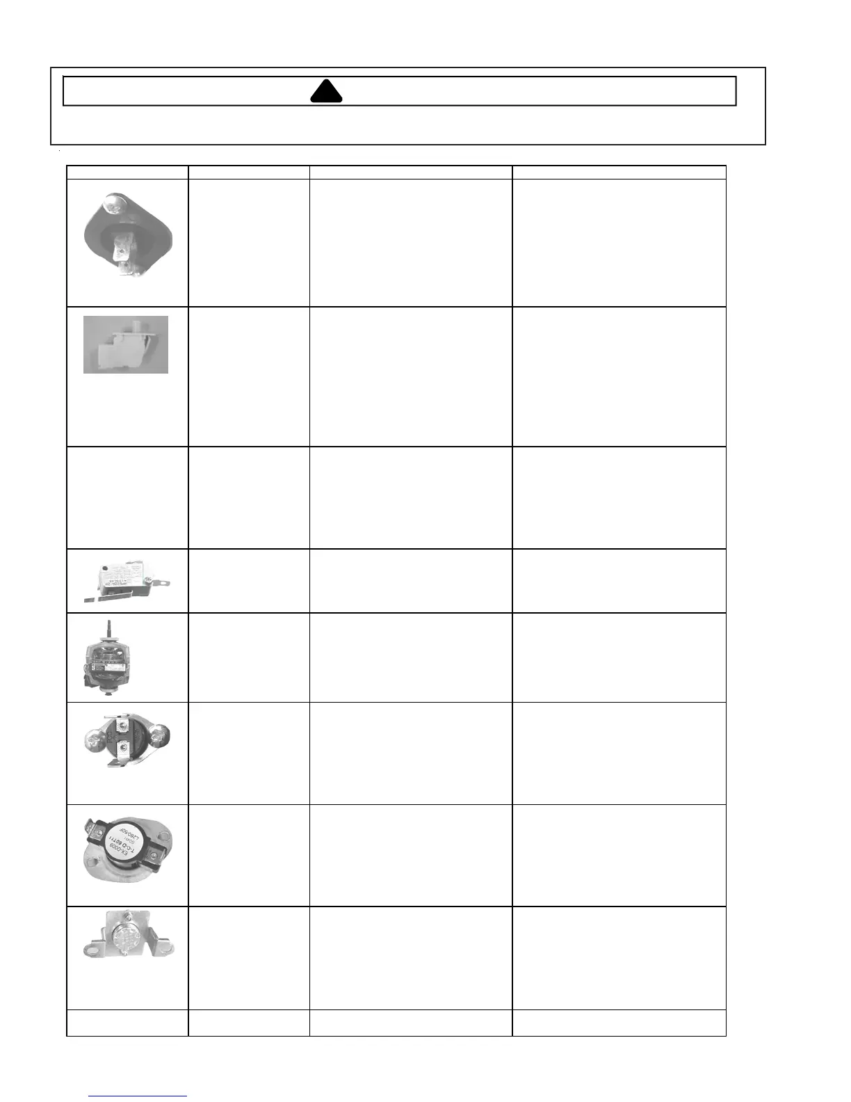
Thermistor Unplug harness connector and test
from wire insertion side.
Pin #2 and Pin #6 of CN6
10000 ohms @ 77
° F/25°C
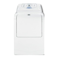
Door Switch Unplug connectors and test switch
terminals.
Door open terminals COM to NC/ 1 to
3
Door open terminals COM to NO/1 to
2
Door closed terminals COM to NC/ 1
to 3
Door closed terminals COM to NO/ 1
to 2
Infinity
Less than 1 ohm
Infinity
Less than 1 ohm
Light Unplug connectors and test switch
terminals.
Check across terminals
80 to 100 ohms
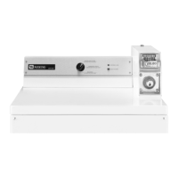
Belt Switch
Unplug connectors and test switch
terminals.
Check across terminals switch closed
Check across terminals switch open
Less than 1 ohm
Infinity
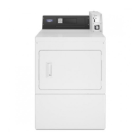
Motor
Unplug harness connector and test
motor circuits.
Pin #4 and Pin #5 (Windings)
Pin #1 and Pin #2 (Centrifugal switch)
2 ohms
Open
Thermostat
185
°F/85°C 25A
Unplug connectors and test
Thermostat terminals.
Check across terminals
Less than 1 ohm
Hi Limit
210
°
F/99
°
C 25A
Unplug connectors and test
Thermostat terminals.
Check across terminals
Less than 1 ohm
Thermal Cut Off Unplug connectors and test
Thermostat terminals.
Check across terminals
Less than 1 ohm
Heater Element Unplug connectors and test Heater
terminals
10 ohms