8-14
F1 - FREQUENCY INVERTER
Pin Wire
F4 Jumper to F5
F5 Jumper to F4
F8 White
F9 Red
F11 Green
GA - DISPLAY CONNECTOR
Pin Wire
Anode Red
Cathode Blue
P1 - INPUT POWER
Pin Wire
P1 L1
P2 Earth
P3 L2
Q1 - MC5 PN - CHEMICAL SUPPLY
Pin Wire Signal
Q1 Black Supply 1
Q2 Red Supply 2
Q3 Pink Supply 3
Q4 Brown Supply 4
Q5 Yellow Supply 5
Q6 Green Supply 6
Q7 Violet Supply 7
Q8 White Supply 8
Q9 Not Used Not Used
Q10 Orange 24VAC
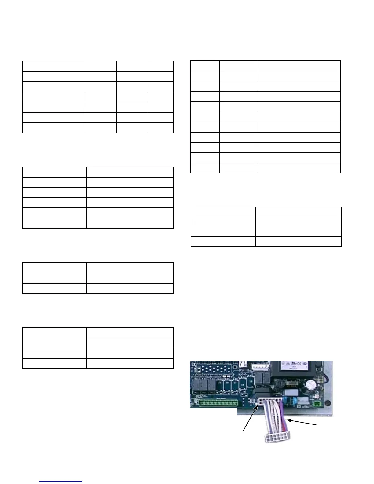
MC4 PD UPGRADE TO MC5 BOARD
Replacing an MC4 control board with an MC5
control board in PD washers requires the
addition of an adapter cable.
DL1 on an MC4 board is a 12 pin connector.
DL1 on an MC5 board is a 14 pin connector.
The adapter cable allows proper connection of
the door lock wire harness cable on the MC5
control board.
Door Lock
Wire Harness
Adapter Cable
MC5
Control Board
DL1
Connector
M1 - OUTPUT VOLTAGE TEST POINT
Pin Output
M1 to M2 MC4 12VDC to Z1
connector Pin #1 (Gnd)
M1 to M2 MC5 24VAC
K1 - PD KEY PAD CONNECTOR
Cycle Contact Contact Button
Whites 4 7 A
Colors 7 9 B
Bright Colors 5 9 C
Perm Press 4 6 D
Quick Wash 6 9 E
Delicates & Knits 4 5 F



 To Next Page