HOW TO USE THIS MANUAL
GI
HOW TO USE THIS MANUAL
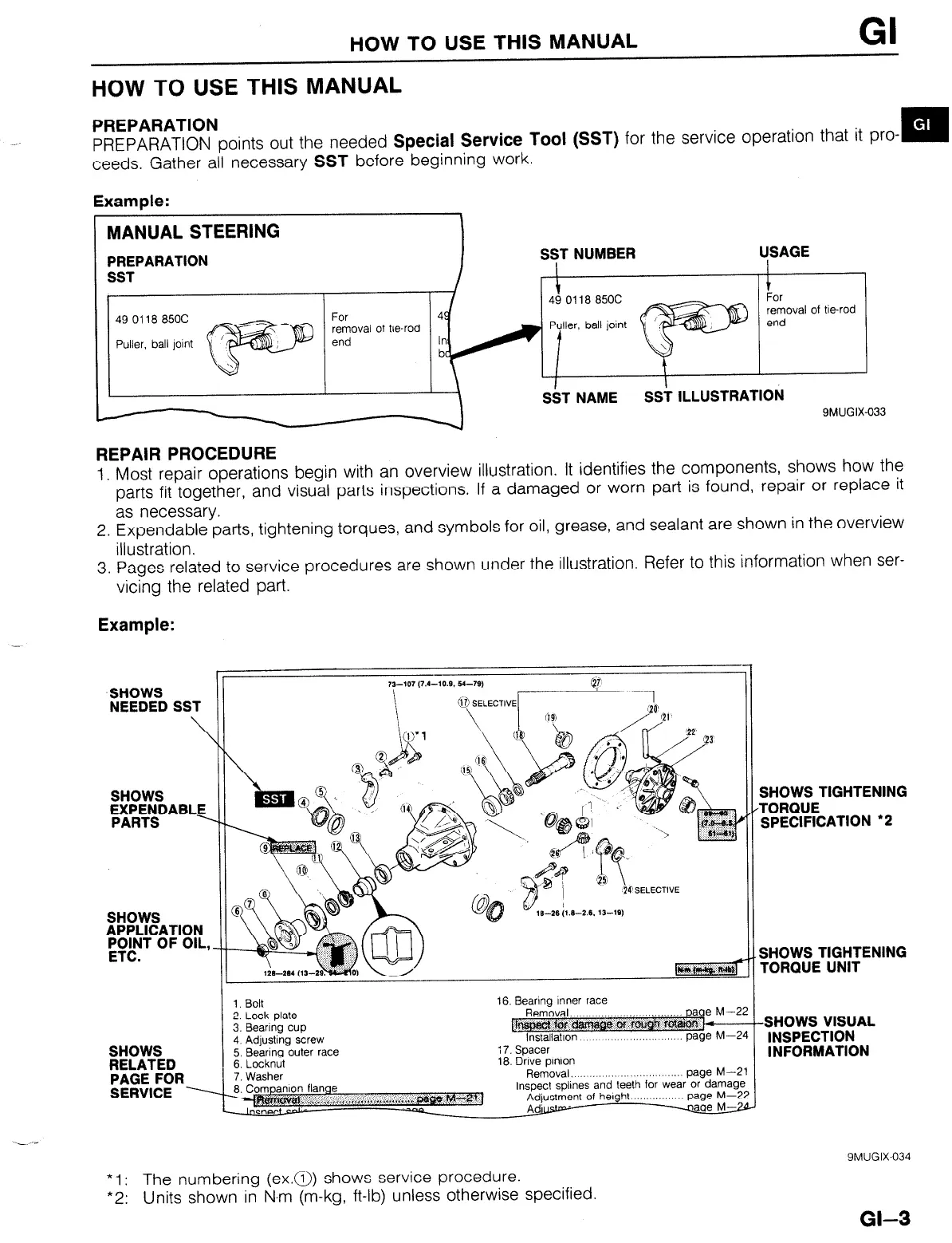
PREPARATION
PREPARATION points out the needed
Special Service Tool (SST)
for the service operation that it pro-
m
ceeds. Gather all necessary
SST
before beginning work.
Example:
49 0118 850C
removal
of be-rod
9MUGIX-033
REPAIR PROCEDURE
1. Most repair operations begin with an overview illustration. It identifies the components, shows how the
parts fit together, and visual parts inspections. If a damaged or worn part is found, repair or replace it
as necessary.
2. Expendable parts, tightening torques, and symbols for oil, grease, and sealant are shown in the overview
illustration.
3. Pages related to service procedures are shown under the illustration. Refer to this information when ser-
vicing the related part.
Example:
SHOWS
NEEDED SST
\
SHOWS
APPLICATION
#T OF OIL,
SHOWS
RELATED
PAGE FOR
SERVICE ----
\
\
3. Bearing cup
1. Bolt
2. Lock Dlate
4. Adjusting screw
5. Bearing outer race
6. Locknut
7. Washer
8. Companion flange
16. Bearing Inner race
@
Removal. ,,,..,,,..
lnstallatlon
page
page M--5
M-Z
i 7. Spacer
18. Drive pinion
Removal, .,,, ,.,, .,......... page M--i
Inspect spllnes and teeth for wear or damagl
Adjustment of height page M-2
Adurstp-
w
SHOWS TIGHTENING
TORQUE
SPECIFICATION ‘2
SHOWS TIGHTENING
rORQlJE UNIT
SHOWS VISUAL
INSPECTION
INFORMATION
* 1: The numbering (ex.a) shows service procedure.
*2: Units shown in N.m (m-kg, ft-lb) unless otherwise specified.
9MUGIX-034
GI-3



 To Next Page