● ✍
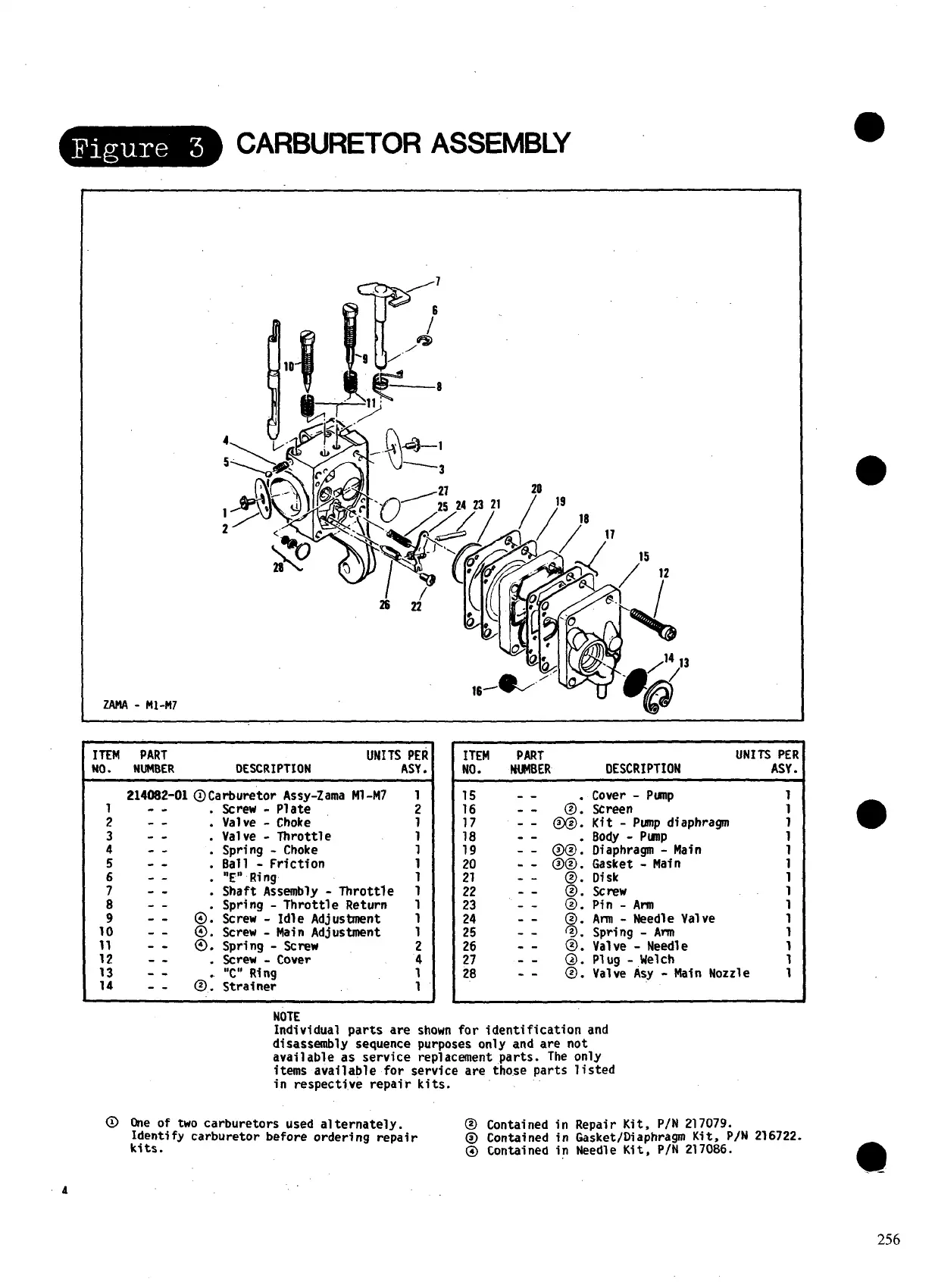
-CARBURETOR ASSEMBLY
2MA -M1-M7
/7
Ffa
6
=4
1—8
:Ar ‘—-----3
4
5
1
2
3
TEM
PART
UNITSA:;R
10. NUMBER
DESCRIPTION .
; :: :
3
..-
.
4
--
.
5
--
.
6
--
.
7
--
.
8
--
9
--
0:
10 --
@.
11 --
@.
12 -- .
13 --
14 --
@:
- 214082-01 @Carburetor Assy-Zama Ml -M7 1
Screw
- Plate 2
Valve
- Choke
Valve -
Throttle
Spring - Choke
Bal 1
- Friction
“E” Ring
Shaft Assembly - Throttle
Spring -
Throttle Return
Screw - Idle Adjustment
Screw
- Main Adjustment
Spring - Screw
screw
- Cover
“C” Ring
Strainer
1
1
1
1
;
1
1
1
2
4
1
1
ITEM
PART
UNITS PEI
NO. NU4BER
DESCRIPTION
ASY
15 -- .
16 --
17
-- &
18 --
19
-- @@:
20
-- @@.
21 --
@.
22 --
@.
23 --
@.
24 --
@.
25 --
~.
:! ::
%
28 --
@.
Cover -
Pump
1
Screen
1
Kit - Pump diaphragm
1
Body - PunP
1
Diaphragm - Main
1
Gasket - Main
1
Disk
1
w rew
1
Pin
- Arm
1
Ann
- Needle Valve
1
Spring - Ann
1
Valve - Needle
1
P1 Ug - Welch
1
Valve Asy - Main Nozzle 1
NOTE
Individual parts are shown for identification and
disassembly sequence purposes only and are not
available as service replacement parts. The only
items available for service are those
parts listed
in respective repair kits.
@ One of two carburetors used alternately.
@ Contained in Repair Kit, P/N 217079.
Identify carburetor before ordering repair
kits.
@ Contained in Gasket/Diaphragm Kit, P/N216722.
@ Contained in Needle Kit, P/N 217086.
A
256
 Loading...