EMCO Load Weigher Installation and Calibration
5-55
5
Installing the Control Unit and Connecting the Wires
The control unit may be mounted using the DIN mounting bracket supplied or using the holes
in the sensor itself. Choose a convenient location on the cartop. (For iControl, if there is space,
the control unit could be mounted inside the iLink enclosure.)
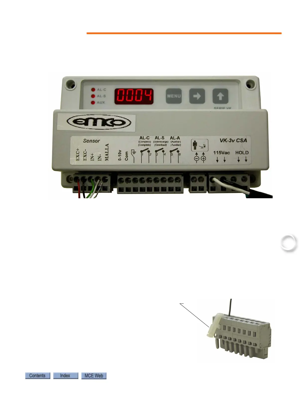
Three sets of wires must be connected to the EMCO VK-3v control unit:
1. a. For iControl, EMCO control unit output to ICE-CTP board in the iLink Cartop box:
• connect CTP board terminal LW- to EMCO control terminal Com.
• connect CTP board terminal LW+ to EMCO control terminal 0-10v.
• connect CTP board terminal SHLD to the cable shield (do not connect the shield to the
EMCO control unit.
1. b. For IMC or Performa, EMCO control unit output, through the traveler, to the control-
ler.
• connect SCR-RI (or SCR-RIX) board terminal LW- to EMCO control terminal Com.
• connect SCR-RI (or SCR-RIX) board terminal LW+ to EMCO control terminal 0-10v.
2. 115Vac power, connected to the terminals labeled 115Vac.
3. Sensor wires, connect the control unit as indicated on the sensor wire:
• red wired to terminal EXC+
• black wire to terminal EXC-
• green wire to terminal IN+
• white wire to terminal IN-
• shield wire to terminal MALLA
Use the Terminal tool/key (wire insertion tool), or
a narrow flat blade screwdriver to open the detent
in the terminal connector to allow insertion of the
tinned wires.