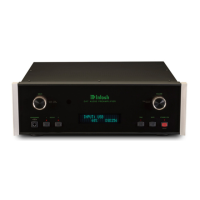
Do you have a question about the McIntosh C12000 Controller and is the answer not in the manual?
Warning against exposing the equipment to rain or moisture to prevent fire or shock risks.
Caution regarding risk of electric shock and prohibition of user-serviceable parts inside.
Instructions to refer servicing to qualified personnel and general handling precautions.
Pin configuration for balanced audio inputs and outputs.
Explanation of connections for controlling power states of other components.
Information on ports for sending remote control signals to source components.
Details on connecting external IR receivers for remote control.
Information on connecting to external third-party controllers via RS232.
Separation of power, control, and audio circuits for enhanced channel isolation and noise reduction.
Utilizes vacuum tube circuitry for phono inputs to minimize noise and distortion.
Allows selection between Solid State and Tube amplification for outputs.
Employs advanced balanced circuitry from input to output for optimal signal integrity.
Features precision RIAA equalization and selectable cartridge loading/gain.
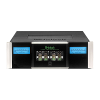
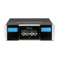
Peak-responding meters indicating the output level of the C12000 Phono Preamplifier.
Electromagnetic switching with level trim for seamless input changes and volume matching.
Facilitates connection with long cable lengths without signal quality loss.
Digitally controlled attenuator system with optical encoder for accurate volume and balance adjustments.
Headphone Crossfeed Director circuitry enhances spatial sound localization for listening.
Front panel display shows source, volume, and setup mode selections.
Enables the unit to function as part of a Home Theater Multichannel Sound System.
Allows system control via remote and external sensor from another room.
Provides convenient turn-on for McIntosh components and assigns trigger outputs.
Two separate regulated power supplies ensure stable, noise-free operation.
Even illumination achieved through strategically placed long-life LEDs.
Features McIntosh illuminated glass and stainless steel chassis for lasting beauty.
Detailed explanation of each numbered connector (1CR-11CR) on the Controller's rear panel.
Detailed explanation of each numbered connector (1PR-15PR) on the Preamplifier's rear panel.
Instructions for connecting power control cables to enable automatic On/Off switching between components.
Details on using data ports for remote operation of source components via the C12000 remote.
Guidance on connecting an external IR sensor for remote operation from another room.
Instructions for connecting audio sources using unbalanced and balanced cables.
Detailed description of the numbered buttons and their operational capabilities.
Explanation of the INPUT, TRIM, VOLUME, INFORMATION DISPLAY, and ADJUST controls.
Description of the HEADPHONES jack and Output Level meters on the Preamplifier.
Instructions on how to check the internal software version of the C12000.
Procedure for enabling/disabling inputs and renaming them for user convenience.
Procedure for switching the C12000 between standby and active modes.
How to change audio sources and adjust the listening level using front panel or remote.
Introduction to various trim adjustments stored per input source.
Adjusting resistance settings to match phono cartridge requirements.
Adjusting capacitance settings to match phono cartridge requirements.
