CINEMA 2, HOME THX AUDIO: TO REPRODUCE DOLBY SURROUND, PRO LOGIC
DECODED MOVIE SOUNDTRACKS WITH HOME THX AUDIO ENHANCEMENT.
The CINEMA 2 or Home THX Audio mode of operation is possible only when the
optional Mcintosh THX-M Module has been installed in the C39.
The four Dolby Pro Logic processed output signals are fed to the Home THX Audio circuits
in the THX-M module for further processing and enhancement which produce the following
six outputs.
Left audio input signals are fed to the LEFT FRONT Unbalanced and LEFT Balanced Out-
puts. Right audio signals are fed to the RIGHT FRONT Unbalanced and RIGHT Balanced Out-
puts. The processing circuits also feed center channel signals which include dialog, to the
Unbalanced CENTER Output. The Dolby Pro Logic decoded monaural surround signals are
then further processed into separate spatially expanded left and right surround signals, which
are fed to the LEFT Surround and RIGHT Surround Unbalanced outputs.
The Left Front, Center and Right Front signals of 80Hz and lower are also combined by
the C39 and fed to the SUBWOOFer Output.
With the Mcintosh THX-M Module installed in the C39, the front panel Home THX Audio
Indicator lights when the MODE Switch is in CINEMA 2 position. The Dolby Pro Logic front
panel indicator stays lit in both CINEMA 1 and CINEMA 2 mode.
All signals fed to the six unbalanced outputs also are fed to corresponding pins
on the rear panel 6 CHANNEL OUTPUT connector.
D. DISPLAY WINDOW
1. The Dolby Pro Logic™ indicator lights when the C39 is switched to CINEMA 1 or
CINEMA 2 Mode.
2. The Home THX Audio indicator lights when the C39 is in CINEMA 2 Mode, and the
optional THX-M Module is installed.
The optional Mcintosh THX-M Module must be installed in the C39 for the Home
THX Audio indicator to light.
3. The % (Percentage), VOLUME indicator always lights when the C39 is turned on and
operating. The selected volume is indicated as a percentage of maximum, with numbers
reading from 0 to 99. The indicator also shows the amount of volume level trim that is used
for each channel during the surround level calibration procedure.
E. LISTEN
Selects any of the 12 audio input program signals that will feed the six Unbalanced out-
puts, the two Balanced outputs and the SIX CHANNEL OUTPUT connector. These are Area
"A" signals. The audio signals for Satellite, TV, Laser Video, VCR1, VCR2 and V-AUX will have
their corresponding Video signals switched simultaneously. The selected LISTEN video signals
will appear at the MON A Video Outputs. You can select either audio only programs for listen-
ing, or audio/video programs for listening and viewing.
The VCR1, VCR2, TAPE 1 and TAPE 2 and Area "B" outputs are not affected by the LISTEN
switch.
F. VOLUME
Adjusts the volume level of all six Unbalanced outputs, the two Balanced outputs and the
6 CHANNEL OUTPUT Connector. These are Area "A" outputs.
10
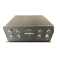
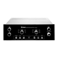
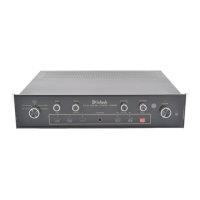
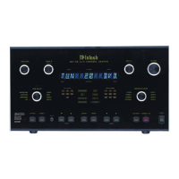
FRONT PANEL
CONTROLS,
SWITCHES
AND
PUSHBUTTONS