IN BYPASS MODE, FOR THE PROGRAM SIGNALS TO BE FED TO THE VCR, TAPE OR
AREA "B" AUDIO OUTPUTS.
8. VCR1, 2 and V-AUX (Auxiliary)
Connect cables from the Audio Outputs of VCR units or other similar Audio/Video ac-
cessories to these three AUDIO INPUTS.
9. LV (Laser Video)
Connect a pair of cables from a Laser Video Disc player Audio Outputs to the LV AUDIO
INPUTS.
10. TV
Connect a pair of cables from the Audio Outputs of a TV set, TV Monitor or TV Tuner to
the TV INPUTS.
11. SAT (SATellite)
Connect a pair of cables from the Audio Outputs of a Satellite TV Tuner or Receiver to the
SAT INPUTS.
12. TAPE1 and TAPE2
Connect a pair of cables from the Outputs of two audio tape recorders to the TAPE1 and
TAPE2 INPUTS.
13. TUNER
Connect a pair of cables from the outputs of an AM/FM Stereo Tuner to the TUNER INPUTS.
14. CD1, CD2
Connect a pair of cables from the output of two CD players to the CD1 and CD2 INPUTS.
For example, CD1 Inputs could be used for a single disc player, and CD2 Inputs for a CD
changer.
When the C39 is used with the CR 10 Remote Control System, only the CD2 input will func-
tion with the CR 10.
15 and 16. AUX (Auxiliary) and PH (PHono)
Both the PHono and Auxiliary inputs are selected by the same position on the front panel
LISTEN and RECORD selector switches. Either the PHono or Auxiliary inputs can be used,
but not both at the same time. When a pair of cables is connected to the Auxiliary input
jacks, the PHono section is automatically bypassed.
Auxiliary: Connect a pair of cables from the outputs of an accessory component to the
AUX INPUTS.
To use the PHono inputs, FIRST remove any cables connected to the AUX inputs.
PHono: Connect a pair of cables from a record player with a moving magnet phono car-
tridge to the PH INPUTS.
AUX: Connect a pair of cables from the high level outputs of an accessory component
to the AUX inputs.
17. GND (Ground)
If the phono player being used has a separate ground lead, connect it to the GND terminal.
18. L and R BALANCED OUTPUTS
Connect cables with XLR type Balanced Connectors from the C39 L (Left) and R (Right)
BALANCED OUTPUT jacks to the balanced input jacks of the power amplifier. Signals at the
17
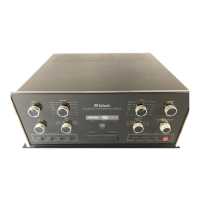
THE
REAR PANEL
AND
HOW TO MAKE
CONNECTIONS