HALL MODE DELAY TIMES
In the HALL operating mode, the time delays are slightly longer than the panel indications.
Set the delay according to your personal preference. The shorter delay times simulate a smaller
room, while the longer delays simulate a large room or concert hall.
FRONT PANEL INDICATION ACTUAL TIME DELAY IN MILLISECONDS
12
16
20 (Recommended Setting)
24
28
16.4ms
32.8ms
49.2ms
65.1ms
81.9ms
O. ACCESS
Press the ACCESS pushbutton to open the motor driven door over the Camcorder and Head-
phone connectors. As soon as the door opens, the rear panel V-AUX VIDEO inputs are switched
to the front panel Camcorder Video inputs. The V-AUX AUDIO inputs are automatically switched
to the front panel Audio inputs when audio cables are inserted into the Camcorder jacks.
Press ACCESS again or turn the front panel VOLUME control to close the door.
P. REC LOCK (RECord LOCK)
Press this pushbutton to disable any remote AREA "B" sensors or keypads. This avoids
the possibility of someone accidentally sending a control signal from AREA "B" that would
disrupt a recording process set up in Area "A". A red LED above the REC LOCK pushbutton
lights to indicate AREA "B" and its sensors are turned off.
Q. MUTE
Press MUTE to silence all six audio output channels in Area "A". A Red LED above the
MUTE pushbutton will blink on and off to indicate that the signals are muted. Press MUTE
again or turn the front panel VOLUME control to restore normal audio operation. The front
panel MUTE does not affect the TAPE or Area "B" Outputs.
Mute Area "B" by using the hand held remote controller transmitting to a wall sensor or
a keypad in Area "B". A red LED will blink on and off in either the wall sensor or a keypad
in Area "B" to indicate the area is muted.
R. POWER
Press POWER to turn on the C39 system. The front panel will illuminate and show the pro-
gram signals and operating modes selected in Area "A". Only the Area A outputs and Area
"A" power amplifier will turn on. The Area "A" power amplifier AC power cord must be con-
nected to, or controlled by, the C39 rear panel Area "A" AC outlet.
Area "B" Outputs and the dedicated Area "B" power amplifier can be turned on
only in Area "B" by a keypad or remote controller transmitting to an Area "B" sensor.
The Area "B" power amplifier AC power cord must be connected to, or controlled by, the
C39 rear panel Area "B" AC outlet.
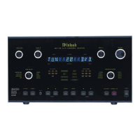
The descriptions and functions of the C39 Remote Controller pushbuttons refer to the
numbers on the drawing.
1. Select any of the 12 Audio and Audio/Video LISTEN program signals in Area "A". Select
any of the same 12 Audio and Audio/Video program signals in Area "B". The selected Area
"B" signals are also the RECORD program signals.
13
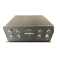
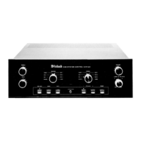
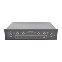
FRONT PANEL
CONTROLS,
SWITCHES
AND
PUSHBUTTONS
C39
HAND HELD
REMOTE
CONTROLLER