THE CHANNEL ALLOCATION IS AS FOLLOWS:
CHANNEL 1
CHANNEL 2
CHANNEL 3
CHANNEL 4
CHANNEL 5
CHANNEL 6
Center Front
Left Surround
Left Front
Right Front
Subwoofer
Right Surround
1. SUR (SURround)
Connect a pair of cables from the SURround AUDIO OUTPUT jacks to the inputs of the
power amplifier channels which will feed left and right surround sound loudspeakers.
2. CENTER
Connect a cable from the CENTER AUDIO OUTPUT jack to the amplifier channel that will
feed a center front loudspeaker.
3. SUBWOOF (SUBWOOFer)
Connect a cable from the SUBWOOFer AUDIO OUTPUT jack to the amplifier channel
feeding a subwoofer loudspeaker. This output includes only audio frequencies of 80Hz and
lower.
4. FRONT
Connect a pair of cables from the FRONT AUDIO OUTPUT jacks to the left and right front
amplifiers. Use these outputs if you are operating the C39 as a conventional two channel
stereo control center.
The same signals that feed the FRONT AUDIO OUTPUT jacks also feed the BALANCED
OUTPUTS, (See No. 18.)
5. VCR1, VCR2
Connect cables from the C39, VCR1 and VCR2 AUDIO OUTPUT jacks to the high level
audio inputs of two VCR units. These connections allow you to record the audio portion of
ANY input selected by the RECORD switch.
6. TAPE 1, TAPE 2
Connect cables from the C39, VCR1 and VCR2 AUDIO OUTPUT jacks to the high level
inputs of two audio tape recorders. These connections allow you to record the audio portion
of ANY input selected by the RECORD switch.
7. RECORD PROCESSOR, FROM and TO
An external signal processor can be added to the C39 which will affect audio recording
signals only at the VCR1, VCR2, TAPE 1 and TAPE 2 audio outputs. The PROCESSOR FROM
jacks have built-in switching contacts that allow normal signals to pass through when no cables
are connected. When an external signal processor is properly connected, the program signals
will feed to the processor from the C39 PROCESSOR TO jacks, and return to the C39 at the
PROCESSOR FROM jacks.
Connect a pair of cables from the external processor Outputs to the C39 PROCESSOR
FROM jacks. Connect another pair of cables from the external processor Inputs to the C39
PROCESSOR TO jacks.
WHEN AN EXTERNAL SIGNAL PROCESSOR IS CONNECTED TO THE C39 RECORD
PROCESSOR JACKS, THE PROCESSOR MUST BE TURNED ON AND OPERATING, OR
16
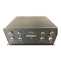
THE
REAR PANEL
AND
HOW TO MAKE
CONNECTIONS