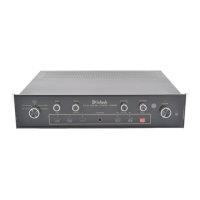
is added to the C712 for the addition of video switching. The MVS-3 must also be connected
to the C712 VIDEO DATA PORT.
8. TUNER
Connect cables from the left and right channel outputs of a tuner to the C712 L (Left) and
R (Right) TUNER INPUTS.
9. CD1 and CD2
Connect a cable from the left channel output of a CD player to the C712 L (Left) CD1 IN-
PUT. Connect a cable from the right channel output to the C712 R (Right) CD1 INPUT. Con-
nect a second CD player to the C712 CD2 inputs in a similar manner.
For example, CD1 inputs could be used for a single play CD player, and the CD2 inputs
for a CD changer.
10. AUX (Auxiliary) / PH (Phono)
Both the PHono and Auxiliary input jacks are selected by the same position on the front
panel INPUT switch. One or the other pair of inputs can be used, but not both simultaneously.
Connect the left channel high level output of any audio accessory unit to the C712, L (Left)
Auxiliary INPUT. Connect the right channel accessory output to the C712, R (Right) Auxiliary
INPUT. When cables are connected to the AUX input jacks, the PHono circuit is automatical-
ly bypassed.
To connect a record player with a magnetic phono cartridge, FIRST, remove any con-
necting cables from the Auxiliary input jacks.
Connect a cable from the left channel turntable output to the C712 L (Left) PHono INPUT.
Connect a cable from the right channel to the C712 R (Right) PHono INPUT.
The C712 phono input circuit is designed to accept the signals from a standard moving
magnet phono cartridge.
11. AC POWER
Connect the AC Power cable to a live 120 volt 50/60Hz AC outlet.
The plug blades are polarized so be certain the plug is fully inserted in the outlet to
prevent blade exposure.
CAUTION: TO PREVENT ELECTRIC SHOCK, DO NOT CONNECT THE POLARIZED AC
PLUG ON THIS UNIT TO AN EXTENSION CORD OR OTHER AC OUTLET THAT IS NOT
DESIGNED TO ACCEPT POLARIZED PLUGS. THE PLUG MUST BE FULLY INSERTED
TO PREVENT BLADE EXPOSURE AND MAINTAIN LINE POLARITY.
12. EXTernal SENSOR
Connect a coaxial cable from the EXTernal SENSOR connector to an R649 Wall IR Sensor,
a WK-1 or WK-2 Keypad. This allows the C712 hand held remote controller to send control
signals to the C712 without aiming it at the C712 front panel. An example would be if the
C712 were installed behind a cabinet door that would block the front panel sensor.
13. TUNER CONTROL
Connect a Mclntosh W102 Tuner Control Cable from the TUNER CONTROL connector to
a connector on a compatible Mclntosh tuner such as the MR7083. This allows you to select
and control tuner operating functions with the C712 hand held remote controller transmitting
to a C712 IR sensor.
14. CD1/CD2 CONTROL
Connect a Mclntosh Model W101 CD control cable from the CD1 or CD2 CONTROL con-
THE REAR PANEL
AND HOW
TO MAKE
CONNECTIONS
9

 Loading...