HOW TO
INSTALL
THE
C712
in maintaining all the system components at the coolest possible operating temperatures.
A custom cabinet installation should provide the following recommended minimum spac-
ing dimensions for cool operation. Allow at least 1-1/2 inches (3.8cm) above the unit so airflow
is not obstructed. Allow 17-1/2 inches (44.5cm) depth behind the mounting panel, which in-
cludes clearance for connectors. Allow 1-1/8 inches (2.9cm) in front of the mounting panel
for knob clearance.
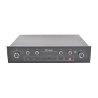
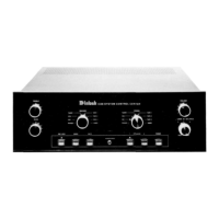
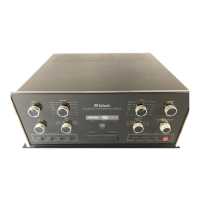
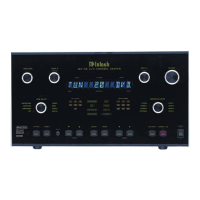
The last page of this manual folds out to show photographs of the front and rear
panels of the C712. This will help you in identifying and locating the controls and
switches on the C712 front panel, and the connectors on the rear panel. The letters
and numbers on the photographs refer to the paragraphs that follow.
A. INPUT
Selects the program source that feeds the MAIN BALANCED, UNBALANCED, TAPE 1 and
TAPE 2 OUTPUTS.
B. BASS and TREBLE
Provide 12dB Boost or Cut with flat response at the center detent position. All tone control
circuit elements are removed from the signal path in the center flat position.
C. BALANCE
The BALANCE control adjusts the volume of the channels relative to each other.
L, (left): Turn the control to the left to accent the left channel by reducing the volume of
the right channel.
R, (right): Turn the right to accent the right channel by reducing the volume in the left channel.
D. LOUDNESS
The LOUDNESS control provides frequency response contoured to compensate for the
behavior of the human ear at softer listening levels. At the fully counterclockwise detent posi-
tion, the frequency response is perfectly flat and the loudness circuit components are removed
from the signal path. Turn the control clockwise to increase frequency compensation in the
correct proportion for proper listening at softer volume levels. The compensated frequency
response is not affected by changes in the volume control settings. First adjust the volume
for the desired listening level, then adjust the loudness control to the setting you prefer.
E. IR SENSOR WINDOW
The IR (Infrared) sensor that accepts IR signals from the C712 Hand Held Remote Controller.
R VOLUME
Adjusts the Volume level from the MAIN BALANCED and UNBALANCED OUTPUTS. The
TAPE OUTPUTS are not affected by the VOLUME control.
G. MONO
Press the MONO pushbutton to add the left and right channel signals together for MONO
signals at the MAIN BALANCED and UNBALANCED OUTPUTS. A Red LED above the pushbut-
ton will light to indicate the MONO mode of operation. The MONO pushbutton does not affect
the TAPE outputs. They are always stereo.
H. TAPE MONitor 1 and 2
Press TAPE MON 1 or 2 to listen to playback of tapes from either of two tape recorders.
FRONT PANEL
CONTROLS,
SWITCHES
AND
PUSHBUTTONS
6