You can listen to previously recorded tapes, or monitor tape from a three-head tape recorder
during the recording process. The TAPE MON pushbuttons operate independently from the
INPUT switch. A Red LED will light above either pushbutton to indicate which TAPE MON has
been selected.
I. HEADPHONES
Plug in a pair of low impedance dynamic headphones to this jack for headphone listening.
Press MUTE on the C712 Remote Controller to mute the main outputs to the power amplifier
to allow private headphone listening. MUTE does not affect the Headphones Output.
J. TAPE COPY, 1 2,2 1
Copy tapes from either of two tape recorders, to each other. The TAPE COPY pushbutton
switches operate independently from the INPUT switch. Use the TAPE MONitor switches to
monitor the output of the recorder playing the original tape, or the recorder making the copy.
A Red LED will light above either pushbutton to indicate which TAPE COPY mode is in use.
The TAPE COPY switches are electronically interconnected to prevent both circuits from
being activated at the same time. If you press one of the TAPE COPY switches to activate
a copy function, you must press the same TAPE COPY switch again before pressing the other
TAPE COPY switch.
K. POWER
Press the red POWER button to turn the C712 system ON. Press again to turn it OFF. The
rear panel SWITCHED AC Outlet turns on with the POWER switch.
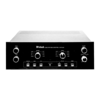
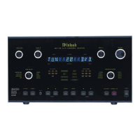
FRONT PANEL
CONTROLS,
SWITCHES
AND
PUSHBUTTONS
Use good quality shielded cables to interconnect the associated equipment used with the
C712. The installation of high quality cables will insure the best possible performance from
your stereo system. Your Mclntosh dealer can advise you on the type and length of cables
best suited for your installation.
1. SWITCHED AC OUTLET
The SWITCHED AC outlet turns on and off with the front panel POWER Switch. Connect
a power amplifier or accessories to this outlet.
The total power capacity of the SWITCHED AC outlet must not exceed 1400 watts
or 11.6 amperes.
To expand the AC capacity of the SWITCHED outlet, add a Mclntosh R612A or PC2 Power
Controller.
2. L and R BALANCED OUTPUTS
Connect cables with XLR type Balanced Connectors from the C712, L (Left) and R (Right)
BALANCED OUTPUT jacks to the balanced input jacks of a stereo amplifier, or two mono amp-
lifiers. Signals at the BALANCED jacks are the same signals as at the Unbalanced MAIN OUTPUTS.
Using balanced connectors and cables can reduce noise and interference by as much as
40dB. This extra noise reduction can be a significant improvement, especially if the cables
are quite long. If two separate mono power amplifiers are used with the C712, balanced cables
can eliminate the possibility of hum pickup. If cable lengths between the C712 and the power
amplifiers are one meter or less, you may find high quality unbalanced cables to be adequate.
Balanced Jack Pin Configuration:
Pin 1. System Ground
Pin 2. + Output
Pin 3. - Output
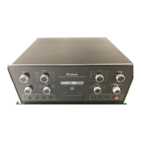
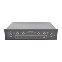
THE REAR PANEL
AND HOW
TO MAKE
CONNECTIONS
7
 Loading...