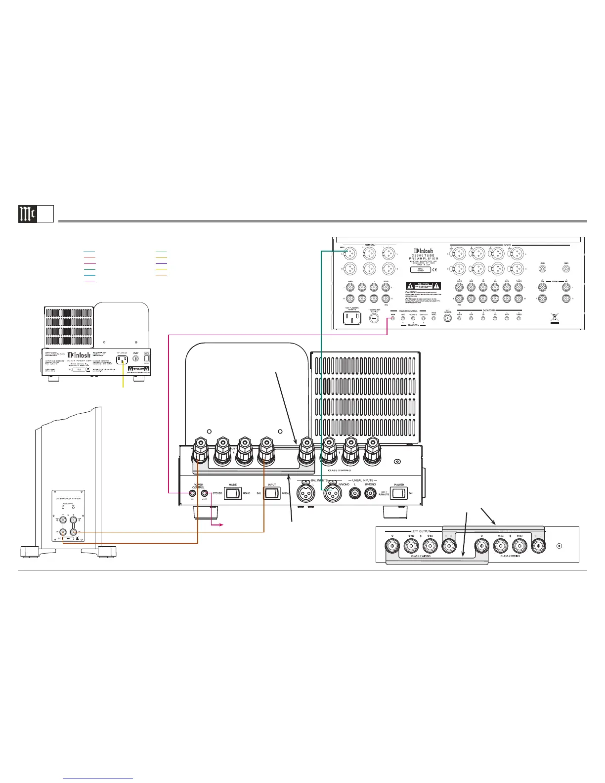
MC275 Monaural Operation Connection Diagram
1B
McIntosh Laboratory, Inc. 2 Chambers Street Binghamton, New York 13903-2699 Phone: 607-723-3512 www.mcintoshlabs.com
Note: Refer to the MC275 Owner’s Manual page 12 for additional connection information.
Connection Legend:
Data Cable*- Digital Signal Cable -
Sensor/Keypad Cable - Network/RS232 Cable -
Power Control Cable* - Ground Wire -
Audio Signal Cable - AC Power Cords -
Video Signal Cable - Loudspeaker Cable -
RF Signal Cable -
* 2 conductor shielded with 1/8 inch stereo mini phone plug on each end.
Audio Preamplifier
Connect to
AC Outlet
Loudspeaker System
JUMPER
BAR
1
(-)
(-)
(+)16Ω
(+)16Ω
To second MC275
1
NOTE: When the Mode Switch is set to MONO, the
supplied Jumper Bars are used to connect the
output of the Left and Right Amplier Chan-
nels in parallel. The effective output imped-
ance of the MC275 Power Amplier is now
8Ω, even though the physical connections are
made to the 16Ω terminals.
The 8Ω terminals would be paralleled when
a 4Ω Loudpeaker is connected to the MC275
(operating in MONO Mode). Likewise the
4Ω terminals would be paralleled when a 2Ω
Loudpeaker is connected to the MC275 (oper-
ating in MONO Mode).
 Loading...