EasyManuals Logo

McIntosh MA6200 Service Information

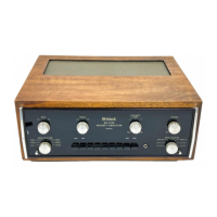
McIntosh MA6200
34 pages
To Next Page IconTo Next Page
To Previous Page IconTo Previous Page
Page #15 background imageLoading...
Page #15 background image
MAó2OO
SCHEMATIC
NOTES
l.
Prínted
circuít board
assemblies
are
outlined on the schematics by dotted
lines.
The
circled
numbers on the
dotted
I ines correspond
to the numbers on
the
pr¡nted
circuit
board layouts.
2.
The
heavy I
ines on the schematics denote
,the
primary
signal
path.
3, The
terminal
numbering
of
rotary
switches
is
for
reference only.
4.
A
dot
on the rotor
of a rotary switch
indicates
that there is an electrical
connection between
the front and
rear
rotor
section.
5.
Unless
otherw¡se
specifled:
Resistance values are
in
ohms,
l/4 watt, and
5%
tolerance.
' Capacitance_values
smal ler than
I are
in
microfarads
(pF);
capac.itance
values
greater
than I
are
in
picofarads (pF);
6.
All voltages indicated
on the schematics
are
measured
under
the following
conditions:
Use
of an
ll megohm input
impedance
VTVM. All
voltages
t
l0% with respect to
ground,
No
signal
at input terminals.
AC input at 120 volts,
50/60
Hz.
Voltages
not specif
ied are
rr0rr
v,ol ts.
7
, Front
panel
control s at:
Mode
Se I
ector
S
tereo
Loudness ccw
Speaker switches
Out
Tape
Mo_nitors Out
Volume
control
Min
Tape
l----+
2
Out
Balance
control
Middle
Tape
2----->
l
Out
Tone
control
s
Flat
I
nput selector
Phono
2
I
To
ad
signa
.3A).
I ì.
s/N BXl00l
to
8X2990:
pushbutton
swi tch
just
output stage bias,
operate
the
ltlA6200
at 120 volts
line input
with no input
l.
Measure the
AC
line input_power
(gpproxlmately 40
watts) or
current
(approximately
The
bias
potentiometers
R85l
and
R852
are
locatðd on
the
þower
output
pC
boards,
.
Turn
both b
iaå
potentiometèrs
ful I couhterclockwi
se.
.
Rotate
bias
adjustment
clockwise
to the
point
where the I ine
input
power
or
current
begins
to increase,
then
back
off
sl ightly to
the
point
where
the
I ine
input
just
reaches i
ts lowest
value.
a
b
9
S/N
10.
c.
Repeat
step b.
for other channel
independentl
y.
S/N BXl00l
to
BXl234:
0n
the
lnterconnect Schematic,
Fl
and
F2
were
wired in the circuit
as shown by dotted
lines.
BXl00l
to
BXI\352
C6
and
C7
were
part
of the
lnterconnect
circuit.
Above S/N
BXl435,
C6
was mounted
on the
rìght
driver
PC
board
as
C836,
and
C7
was mounted
on the left-'
driver
PC
board
as
C835. The
driver
PC
board
assembly number
without
C835
and
C836
is 045219.
0n
PC
the
lnterconnect
schematic,
there is no connection between
board
045260,
pin
42, and
Power Supply
PC
board
pin
14.

Other manuals for McIntosh MA6200

Questions and Answers:

Question and Answer IconNeed help?

Do you have a question about the McIntosh MA6200 and is the answer not in the manual?

McIntosh MA6200 Specifications

General IconGeneral
Power Output75 watts per channel into 8 ohms
Output Impedance8 ohms
Frequency Response20Hz to 20kHz +0, -0.5dB
Input Sensitivity2.5mV (MM), 250mV (line)
Input Impedance47k ohms (phono), 100k ohms (high level)

Related product manuals