1. The heavy lines on the schematics denote the primary
signal path.
2. Unless otherwise noted, all voltages indicated on the
schematics are measured under the following condi-
tions:
a. AC input at 120 volts, 50/60Hz
b. All voltages are +\-10% with respect to ground. A
high impedance (10megaohm) voltmeter must be
used.
3. Unless otherwise specified:
a. Resistors values are in ohms.
b. Capacitor values are in microfarads (uF).
c. Inductor values are in microhenries (uH).
4. On PC Board Drawings, Square Pad Indicates:
a. Polarized Capacitors - Positive
b. Diode - Cathode
c. Others - Pin 1
5. The voltages enclosed in a box are signal voltages that
are measured with a 2.5mV, 1kHz signal connected to
both channels at the TUNER input jacks.
NOTES
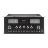
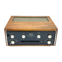
MA6500
Front panel controls are set at:
BALANCE ....................................CENTER DETENT
TREBLE BASS .............................CENTER DETENT
INPUT SELECTORS ...................................... TUNER
LOUDNESS .......................................................... OFF
POWER ................................................................... ON
VOLUME .................................FULLY CLOCKWISE
MONO................................................................... OFF
SPEAKER SWITCHES 1 AND 2........................... ON
Rear panel controls are set at:
PROCESSOR ........................................................OUT
PWR AMP INPUT ................................................. INT
SPEAKER TERMINALS .................... NO LOAD ON
OUTPUTS
6. WARNING:
Parts marked with the symbol have critical
characteristics. Use ONLY replacement parts recom-
mended by the manufacturer.
3