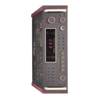
The MAC 4200 may be used on a shelf or table top in
the enclosure in which it comes or may be installed in a
custom cabinet. In any method of use provide adequate
ventilation.
The trouble-free life of any electronic instrument is
greatly extended by providing sufficient ventilation to pre-
vent the build-up of heat that causes deterioration of
component parts. Allow enough clearance so cool air can
enter at the bottom of the receiver and be vented from
the top and rear. The feet installed on the bottom of the
receiver must be left in place when using a shelf or table
top installation. The feet raise the receiver above the
mounting surface to allow reasonable ventilation. If
temperatures increase due to restricted ventilation or
speaker mismatch, an automatic temperature sensing
device turns off the MAC 4200. The device operates
automatically at a preset temperature. The MAC 4200 will
turn on again when the temperature has returned to nor-
mal limits. This additional feature assures complete
reliability under the most extreme operating conditions.
INSTALLING THE MAC 4200
IN A CUSTOM CABINET
The MAC 4200 is installed from the front of a custom
cabinet. The space needed behind the cabinet panel is
15"(38.1cm) deep, 18-1/2" (47cm) wide, and 6" (15.2cm)
high by 17-9/16" (44.6cm) wide. The cabinet panel must
be cut out 5-1/16" (12.9cm) high. Make this cutout careful-
ly. The receiver's front panel has a 1/8" (.32cm) overhang
on both sides and a 3/32" (.24crn) overhang on the top
and bottom, (see Fig. 1)
The weight of the receiver must rest on a shelf in the
custom cabinet with a 15" (38.1cm) x 8" (20.32cm) ven-
tilation hole cut out. (see Fig. 2) In addition, a single 3/8"
to 1/2" (1cm to 1.3cm) diameter hole (see Fig. 2 and Fig.
3) must be drilled in the shelf. A screw inserted through
this hole secures the receiver after installation. The top of
the shelf must be flush with the bottom of the custom
panel cutout.
Fig. 1 Custom Cabinet Front Panel Cutout
Prepare the MAC 4200 for custom mounting by remov-
ing the wood sides and feet:
1. Remove 4 screws; two from each side panel and
remove the panels.
2. On the bottom of the receiver are the 4 plastic feet
held on by screws. Remove these feet. Do not attempt
to remove the 4 plastic button glides as these rest
against the shelf, (see Fig. 2 and 3) At this point the
receiver is ready to be installed.
From the front of the cabinet, thread the power cord
through the opening in the cabinet panel and slide the
MAC 4200 on to the shelf. Adjust the position to evenly
cover edges of the panel cutout. Lock the unit in place
with a screw and washer inserted through the drilled hole
in the mounting shelf (see Fig. 3). Use a 1-1/4" (3.2crn)
screw for 1/2" (1.3cm) shelf or a 1-1/2" (3.8cm) screw for
3/4" (1.9cm) shelf. Do not use longer screws since they
will contact electrical circuits which can lead to equip-
ment failure and possible injury.
Fig. 1 Custom Cabinet Front Panel Cutout
Fig. 2 Custom Cabinet Shelf Mounting Cutout
Fig. 3 MAC 4200 Custom Mounting Profile
4 INSTALLATION

 Loading...