4
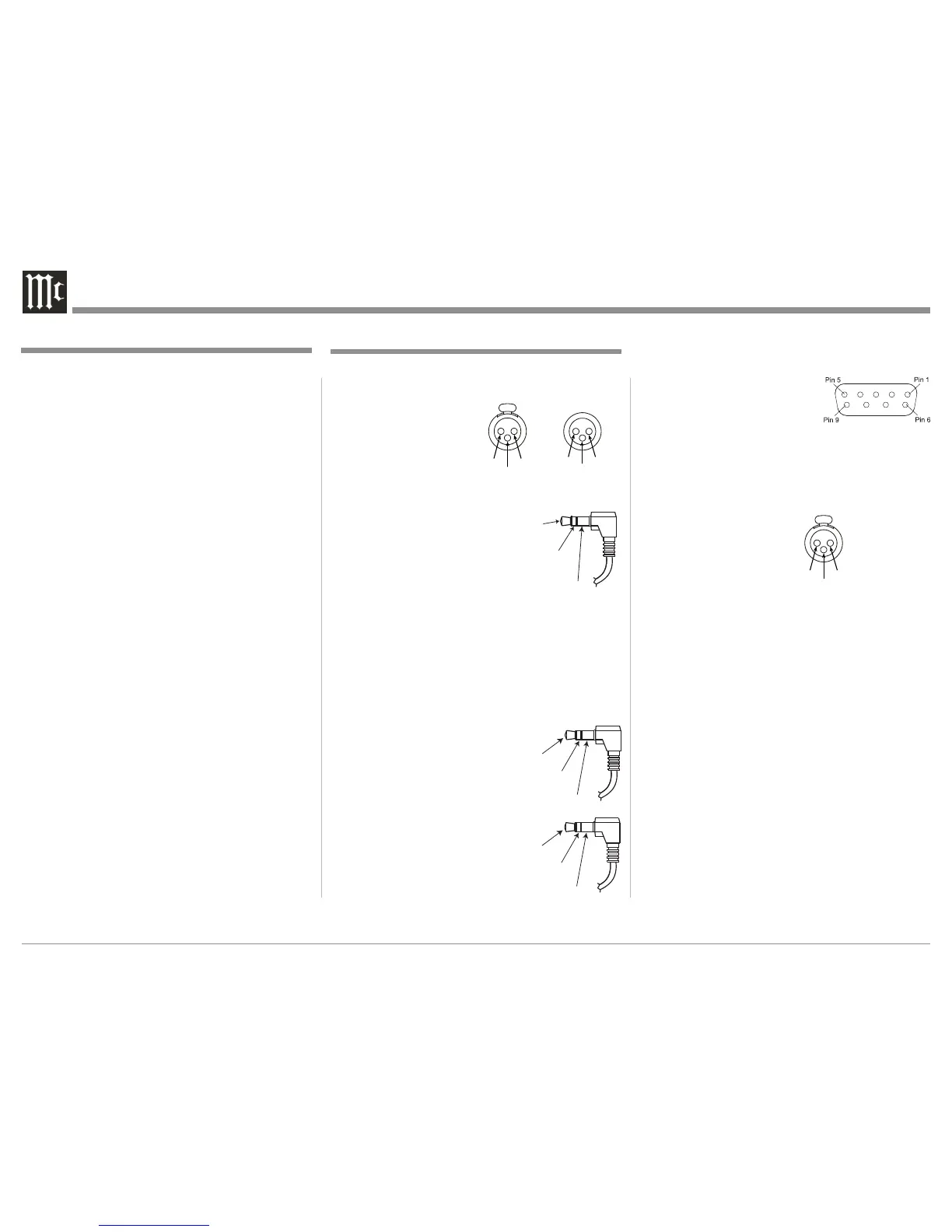
XLR Connectors
Below is the Pin configuration for the XLR Balanced
Output Connectors on the MEN220. Refer to the dia-
grams for connections:
PIN 1: Shield/Ground
PIN 2: + Signal
PIN 3: - Signal
Power Control Connectors
The MEN220 Power Control Input/Output Jacks
receive/send Power On/Off
Signals when connected to
other McIntosh Components. A
1/8 inch stereo mini phone plug
is used for connection to the
Power Control Input/Output on
the MEN220.
Note: The Data and Power Control Connecting Cable is
available from the McIntosh Parts Department:
Data and Power Control Cable Part No. 170-202
Six foot, shielded 2 conductor, with 1/8 inch stereo
mini phone plugs on each end.
Data and IR Input Port Connectors
The MEN220 Data In Port re-
ceives Remote Control Signals. A
1/8 inch stereo mini phone plug is
used for connection. The IR Port
also use a 1/8 inch stereo mini
phone plug and allow the connec-
tion of other brand IR Receivers
to the MEN220.
Connector and Cable Information
Table of Contents
Safety Instructions ..................................................... 2
Thank You and Please Take a Moment ...................... 3
Technical Assistance and Customer Service ............. 3
General Information .................................................. 3
Table of Contents ....................................................... 4
Connector and Cable Information ............................. 4
Introduction ................................................................ 5
Performance Features ................................................ 5
Dimensions ................................................................ 6
Installation ................................................................. 7
Connections:
Rear Panel Connections .............................................8
How to Connect the MEN220 .............................. 9-12
Remote Control:
Remote Control Push-buttons .................................. 14
How to use the Remote Control ............................... 15
Front Panel:
Front Panel Displays, Controls and Push-buttons .... 16
Setup:
How to Operate the Setup Mode ............................. 17
Default Settings........................................................ 17
Input Connection Settings ....................................... 18
System Connection Settings .................................... 18
Output Settings ........................................................ 19
Advanced Settings ................................................... 22
RoomPerfect ............................................................ 24
Operation:
How to Operate the MEN220 ............................. 28-29
Additional Information:
Specifications ........................................................... 30
Packing Instruction .................................................. 31
 Loading...