10
How to Connect with Optional Tuner Module
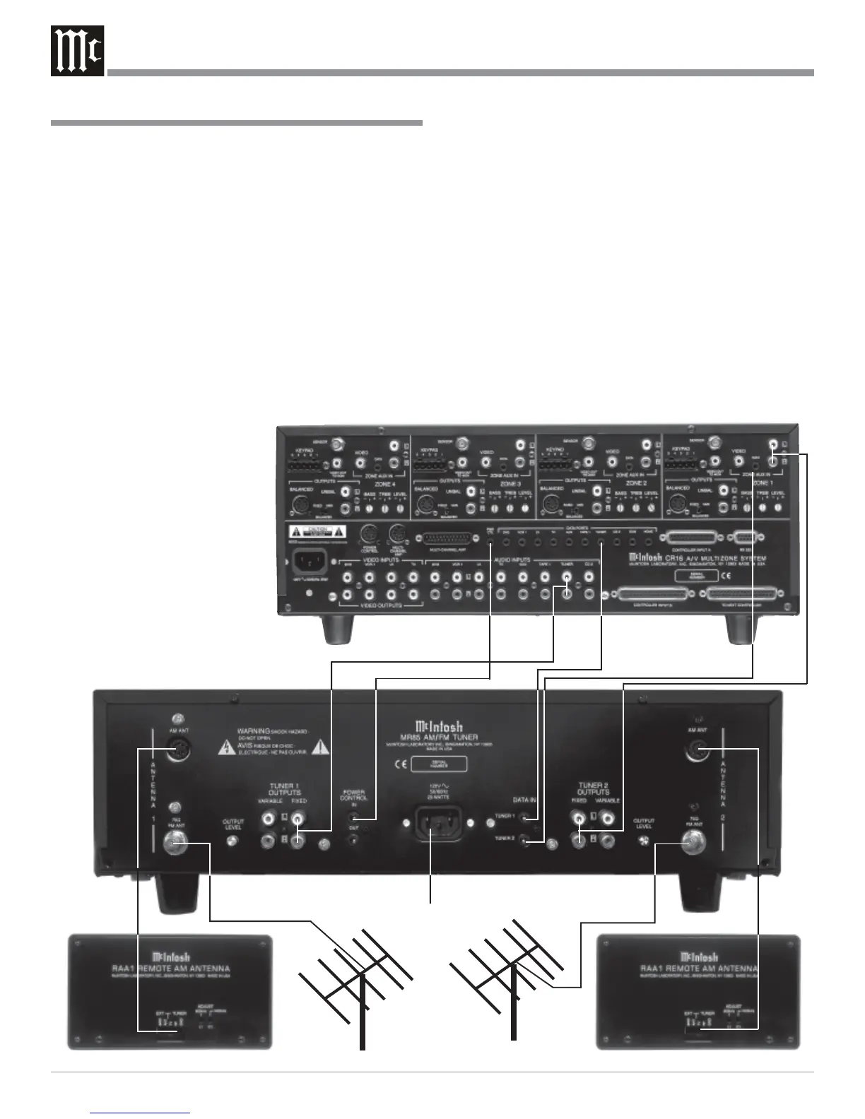
How to Connect with Optional Tuner Module
1. Connect a data cable from the TUNER 1 DATA IN jack
to the TUNER DATA PORT of a McIntosh Multizone
Control Center.
Note: Remote Control operation of the Tuner is made
possible with a Data Cables connected between the
MR85 and a McIntosh Control Center or
Preamplifier. If the MR85 Tuner is connected to a
non-McIntosh Preamplifier, remote control
operation is still possible with an appropriate
interface and McIntosh Remote Control. Contact
your McIntosh Dealer for additional details.
2. Connect a data cable from the TUNER 2 DATA IN jack
to the LOCAL ZONE 1 AUX IN DATA PORT of a
McIntosh Multizone Controller.
3. Connect a power control cable from the POWER CON-
TROL IN jack to the POWER CONTROL OUT of a
McIntosh Multizone Control-
ler.
4. Connect an audio cable from
the TUNER 1 FIXED OUT-
PUTS to the TUNER INPUTS
of a McIntosh Multizone Con-
trol Center.
Note: An optional connection
would be to use the
TUNER 1 VARIABLE
OUTPUTS.
5. Connect an audio cable from
the TUNER 2 FIXED OUT-
PUTS to the LOCAL ZONE 1
To AC Outlet
AUX IN AUDIO Jacks of a McIntosh Multizone Con-
troller.
Note: An optional connection would be to use the TUNER
2 VARIABLE OUTPUTS.
6. Connect the FM Antenna(s) or Cable (from the Cable
Company) to the MR85 Tuner 75Ω (Ohm) FM
ANTenna connector for both Tuner 1 and 2.
Note: If the same FM Antenna or Cable (from the Cable
Company) is used for both Tuner 1 and 2, a suitable
coaxial splitter must be utilized.
7. Connect with the supplied cables, from the 5 Pin Socket
of the McIntosh RAA1 Remote AM Antenna to the
MR85 Tuner RAA1 AM ANTenna DIN Sockets for
both Tuner 1 and 2.
8. Plug the MR85 AC Power Cord into an AC Outlet.
McIntosh Multizone Controller
 Loading...