EasyManua.ls Logo

mcmurdo S20 User Manual

mcmurdo S20
10 pages
To Next Page IconTo Next Page
Page #1 background imageLoading...
Page #1 background image
Orolia Ltd, Silver Point, Airport Service Rd, Portsmouth, Hants, PO3 5PB, United Kingdom
Tel: +44 (0) 23 9262 3900 Fax: +44 (0) 23 9262 3998 Email: service.uk@mcmurdogroup.com
Page | 1
SERVICE BULLETIN
Issue No: MG018 Date: 22
nd
January 2016
McMurdo S20 & Kannad Marine R10 AIS MOB Devices
Battery change & maintenance instructions
INTRODUCTION
1.1 Scope:
This document provides the instructions to enable routine servicing
of the S20 & R10 AIS MOB units.
1.2 Servicing equipment:
The following tools and equipment are required to carry out the
servicing detailed in this manual. Only authorised and trained
people are allowed to perform maintenance & service on these products. We advise it is
good practice that records of any maintenance or service performed are maintained.
Equipment:
AIS receiver
Hand tools:
Calibrated torque driver with attachments: 60 cNm
Small cross-headed screwdriver (No. 1 Pozidrive)
1.3 Antistatic precautions:
The electronics section of the product is sensitive to electrostatic discharge (ESD) which can
cause Immediate or hidden long term damage. It is important that the PCB is only handled
under suitable Antistatic conditions.
A fully grounded workstation, which has conductive surfaces to avoid the build-up of static
charge, should be used.
As a minimum, the operator must be connected to a good earth point through a resistance
of 1MOhm. This is usually achieved by wearing a suitable wrist strap.
1.4 Safety notices:
The product has been assessed as presenting negligible hazard in a sealed serviceable state.
Question and Answer IconNeed help?

Do you have a question about the mcmurdo S20 and is the answer not in the manual?

mcmurdo S20 Specifications

General IconGeneral
Brandmcmurdo
ModelS20
CategoryCamera Accessories
LanguageEnglish

Summary

Introduction and Safety

1.1 Scope

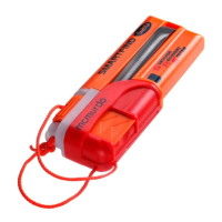
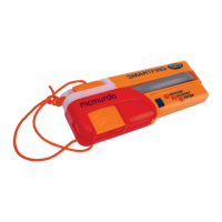
This document provides instructions for routine servicing of the S20 & R10 AIS MOB units.

1.2 Servicing Equipment

Lists required tools and equipment for servicing. Authorised personnel only.

1.3 Antistatic Precautions

Details precautions for handling electronics sensitive to electrostatic discharge (ESD).

1.4 Safety Notices

States the product presents negligible hazard in a sealed serviceable state.

1.5 Safety Analysis

Summarises hazards present when the unit is opened or serviced.

1.6 Hazard Identification Precautions

Identifies hazards like lithium battery risks, biological, RF, and radiation.

1.7 Battery Kit Contents

Lists the items included in the battery replacement kit.

Disassembly Procedure

2.1 Activation Cap Removal

Remove activation cap, switch off beacon, note operation time limit.

2.2 LED Cap Removal

Remove LED cap by unscrewing two screws.

2.3 Battery Removal

Remove the battery; PCB and foil insert do not need removal. Dispose of battery properly.

Assembly Procedure

3.1 Foam Pad Installation

Ensure foam pad is fitted to the bottom of the cell pack.

3.2 Gasket Installation

Ensure replacement sealing gasket is fitted correctly to the LED cap assembly.

3.3 PCB Seating

Ensure the PCB assembly is seated correctly.

3.4 Battery Installation

Fit battery assembly, position wires, connect battery to PCB, avoid damaging foil.

3.5 Battery Counter Reset

Press battery counter reset button; LED and buzzer confirm reset.

3.6 LED Cap Reattachment

Fit LED cap, ensure wires are not trapped, secure with 2 screws torqued to 60cNm.

3.7 ON/OFF Test

Perform ON/OFF test to check beacon functionality and switch-off behaviour.

Leak Test and Drying

4.1 Overview

Recommends gross leak test in warm water before full function test.

4.2 Instructions

Details steps for leak testing, including immersion, air removal, and bubble observation.

4.3 Drying Times

Specifies oven drying times for component parts and battery pack after leak test.

Labelling and Final Assembly

5.1 Battery Date Label

Fit new battery date/over-stick label, check serial and TX ID legibility.

6.1 Activation Cap Reattachment

Fold the antenna around body & reattach the activation cap.

Long Test Procedure

7.1 Overview

Full system check including GPS activation and live test message transmission.

7.2 Instructions

Details steps for performing the long test and verifying success.

Pull Lanyard Rigging Check

8.1 Overview

Activation Cap should look like shown with pre-tied knot inside.

8.2 Instructions

Details how to attach the arming tab and test the auto switch.

Lanyard Rigging Methods

9.1 Manual Activation Rigging

Unit rigged for manual-only activation using a fisherman's bend knot.

9.2 Semi-Automatic Rigging Note

Note on semi-automatic rigging per lifejacket manufacturer guidance.

Related product manuals