IOM 686 AGZ 030A through 065A 41
Zone Temperature (optional Zone Temperature Sensor )
When selected, a Zone Temperature Sensor is connected to TB-7 terminals #134 and #135. Four
variables are used to setup the reset ramp that calculates the Actual Leaving Water Setpoint. These are:
Leaving Water Dial Setpoint (AI-4), Reset Band SP selected with the Zone Terminal, Zone
Temperature High Limit (ZTHL), and Zone Temperature Reset Band (ZTRB).
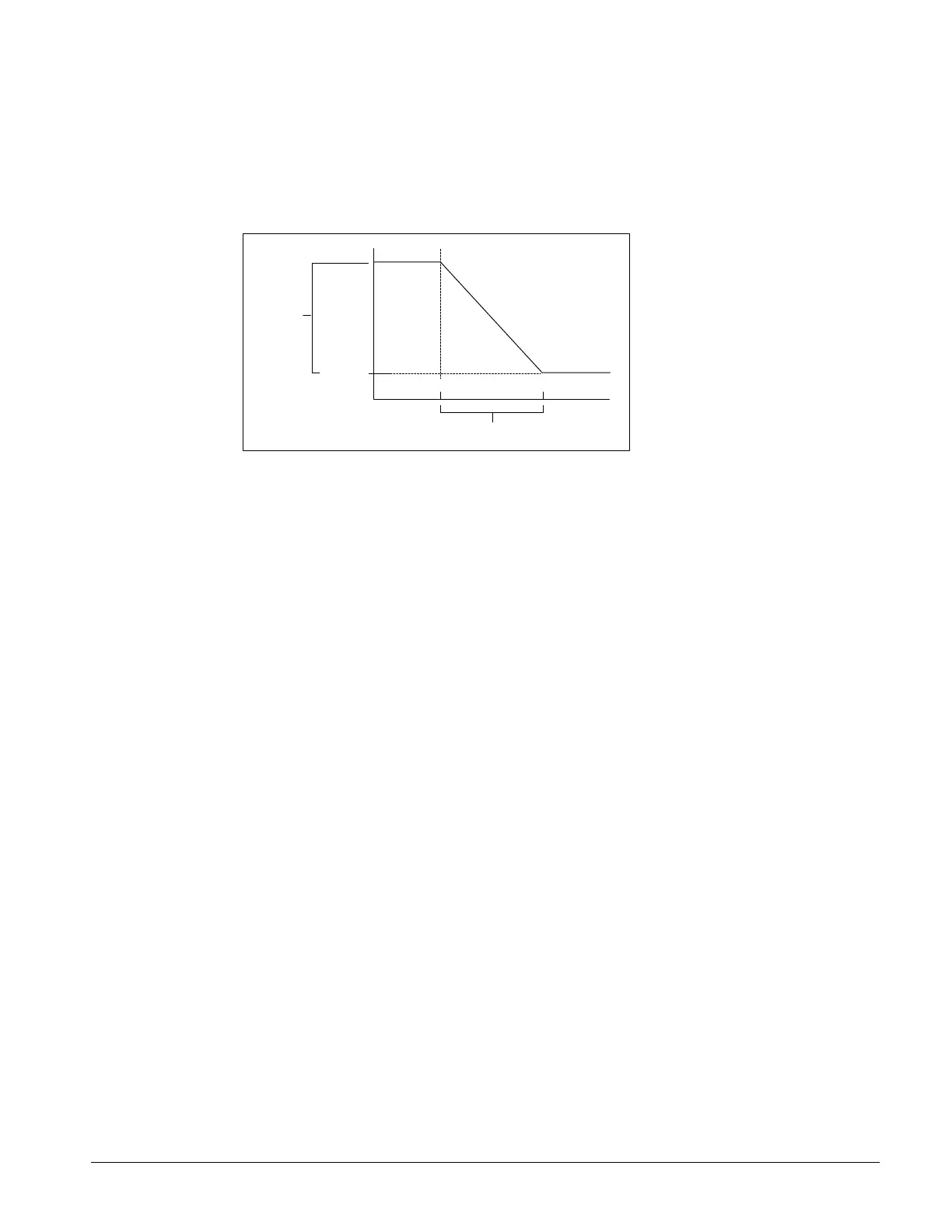
Figure 20, Zone Temperature Reset
LW RB
LW S P
Z TL L Z T HL
Z T RB
(Z TL L= Z TH L
-
Z TR B)
As the Zone Temperature increases above the Zone Temperature Low Limit (ZTLL), the controller
decreases the Actual Leaving Water Setpoint from its Leaving High Limit (Leaving Water Setpoint plus
Leaving Reset Band) to the Leaving Water Setpoint. When the Zone Temperature reaches the ZTHL,
the Actual Leaving Water Setpoint equals the Leaving Water Setpoint (AI-4). If the Zone Temperature
sensor is missing or unreliable, no reset occurs and the Actual Leaving Water Setpoint equals the
Leaving Water Setpoint. If the Leaving Water Sensor (AI-1) becomes unreliable, the compressor
command is forced to 0%.
The Zone Terminal is required to activate and change the reset values.
Remote Reset (2 to 10VDC input)
When selected, a 2 to 10VDC signal is connected to TB-7 terminals #134 and #135. This input can be
achieved by using a 4-20mA signal and conditioning it with a 500 ohm resistor. This input resets the
leaving water temperature to a higher value based on the reset input signal magnitude. At a 2VDC
(4mA) chiller signal input, the controller uses the Setpoint Dial setting. At a 10VDC (20mA) signal
input, the controller adds the reset value to the Dial Setpoint for the controlling temperature.
Between 2VDC and 10VDC, a proportional value is added to the Dial Setpoint for the controlling
temperature. The leaving water temperature can be reset upwards an additional 15
o
F. The Zone
Terminal is required to change the reset values.
Demand Limit (0 to 10VDC input)
When selected, a 0 to 10VDC signal is connected to TB-7 terminals #134 and #135. This input limits
the cooling capacity (0 to 100%). At 0VDC signal input, the controller does not limit compressor
staging. At 10VDC signal input, the chiller would be off. Between 0VDC and 10VDC, a
proportional percentage capacity is available.
Additional Global UNT Controller Features
Remote Stop/Start
When the remote stop/start switch is open, the controller will be in the unoccupied mode. The unit
will be enabled when the remote start / stop switch is closed and will control at the leaving water
temperature setpoint.

 Loading...


