EasyManua.ls Logo

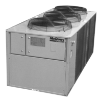
McQuay AGZ 010BS User Manual

McQuay AGZ 010BS
68 pages
To Next Page IconTo Next Page
Page #1 background imageLoading...
Page #1 background image
Installation, Operation and Maintenance Manual
IOMM AGZB1
Group: Chiller
Part Number: 331975001
Effective: October 2007
Supersedes: New
Air-Cooled Scroll Compressor Water Chillers
AGZ 010BS AGZ 034BS, Packaged Chiller
AGZ 010BM – AGZ 034BM, Remote Evaporator
10 to 34 Tons, 35 to 120 kW
R-22, R-407C
60 Hertz
Software Version AGZSU0102D

Table of Contents

Questions and Answers:

McQuay AGZ 010BS Specifications

General IconGeneral
BrandMcQuay
ModelAGZ 010BS
CategoryChiller
LanguageEnglish

Summary

Introduction

General Description

Describes the McQuay air-cooled scroll compressor water chillers as self-contained refrigerating units.

Inspection

Instructions for checking units for damage and verifying nameplate information upon arrival.

Installation

Notes that installation must be performed by trained, experienced personnel familiar with codes.

Handling

Guidance on careful handling of the unit, using lifting slots and spreader bars.

Location

Unit Placement

Details on mounting units on roofs or ground level, foundation requirements, and orientation relative to wind.

Service Access

Information on ensuring accessibility to end-mounted components like compressors and control boxes.

Clearances

Sound Isolation

Guidance on reducing noise transmission in sound-sensitive areas using isolation techniques.

Vibration Isolators

Chilled Water System

Water Piping

Recommendations for installing water piping, including vibration eliminators, shutoff valves, and air vents.

System Volume

Importance of adequate water volume for chiller stabilization and avoiding operational problems.

Variable Chilled Water flow

States that variable chilled water flow systems are not recommended for this equipment.

Flow Switch

Instructions on mounting and connecting a water flow switch to shut down the unit if flow is interrupted.

Water Connections

Details on the unit's 3-inch holes for chilled water piping entry and insulation requirements.

Refrigerant Charge

Information on the operating charge for R-22 or R-407C units and where to find specific data.

Unit Component Location

Diagram showing the location of key components within the unit.

Glycol Solutions

Evaporator Water Flow and Pressure Drop

Explains how glycol affects unit capacity and pressure drop, and how to measure flow and pressure.

R-407C Units

Lubrication

Details on POE lubricants, their properties, and handling precautions for R-407C units.

Pressure/temperature relationship

Procedures for determining superheat and subcooling for R-407C, referencing P/T charts.

Control and alarm settings

Notes that software settings are factory-set for R-407C to account for pressure/temperature differences.

Charging procedures

Guidance on recharging R-407C units, including handling refrigerant as a liquid and initial charge amounts.

Control Layout and Operation

Control Center

Description of the weatherproof control center, its sections, and components.

Start-up and Shutdown

Procedures and checks for unit start-up and shutdown sequences.

Start-up and Shutdown

Pre Start-up

Checklist of procedures before unit start-up, including flushing, checks, and waiting period.

Start-up

Steps to set temperature controller and Delta-T to initiate the unit start-up sequence.

Sequence of Operation

Details on unit start-up sequence, compressor staging, and checks after running.

Equipment Protection Alarms

Lists conditions that shut down or limit unit operation, such as no water flow or high pressure.

Unit Enable Selection

How to enable unit operation via keypad, digital input, or Building Automation System.

Unit Mode Selection

Options for selecting unit operation mode (cooling, ice, glycol, test).

Condenser fan control

How the MicroTech II controller manages condenser fans based on discharge pressure.

Shutdown

Describes the sequence for normal unit shutdown, including compressor staging and crankcase heaters.

Physical Data (Packaged Chillers)

AGZ-BS, R-22/R-407C

Table of physical data for AGZ-BS packaged chillers, including dimensions, weights, and capacities.

AGZ 020BS through 034BS, Packaged, R-22/R-407c

Table of physical data for larger AGZ-BS packaged chillers, covering capacities and specifications.

Physical Data (Remote Evaporators)

AGZ-BM, R-22/R-407C

Table of physical data for AGZ-BM remote evaporator units, listing dimensions and weights.

AGZ 020BM through 034BmS, Remote Evaporator, R-22/R-407c

Table of physical data for larger AGZ-BM remote evaporator units, including capacities and specifications.

Electrical Data

Field Wiring

Guidance on field wiring, compliance with codes, and power connection requirements for AGZ units.

R-22

Electrical data table for AGZ units using R-22 refrigerant, detailing power supply and wiring.

Compressor and Condenser Fan Motor Amp Draw, R-22

Table showing amp draw for compressors and fan motors for R-22 units.

Field Wiring Data, R-22

Field wiring data for R-22 units, covering terminal amp ratings, disconnect sizes, and breaker types.

R-407C

Electrical data table for AGZ units using R-407C refrigerant, detailing power supply and wiring.

Compressor & Fan Motor Amps, R-407C

Amp draw table for compressors and fan motors for R-407C units.

Field Wiring Data, R-407C

Field wiring data for R-407C units, including terminal amp ratings, disconnect sizes, and breaker types.

Notes for Electrical Data

Notes for Compressor and Condenser Fan Amp Draw

Clarifications on RLA and FLA values used for wiring and fan motor amp calculations.

Notes for Field Wiring Data

Clarifications on disconnect requirements, wire material, and wire size temperature rating.

Typical Field Wiring Diagram

Dimensions & Weights (Packaged Units)

AGZ 010BS - 017BS, Packaged

Diagram showing dimensions and weight information for AGZ 010BS to 017BS packaged units.

AGZ 020BS - 034BS, Packaged

Diagram showing dimensions and weight information for AGZ 020BS to 034BS packaged units.

Dimensions & Weights (Remote Evaporators)

AGZ 010 - 017BM Remote Evap.

Diagram showing dimensions and weight information for AGZ 010BM to 017BM remote evaporator units.

AGZ 020BM - 034BM

Diagram showing dimensions and weight information for AGZ 020BM to 034BM remote evaporator units.

Remote Evaporators

Remote Evaporators, for AGZ 010BM – 034BM

Diagram and table detailing dimensions and connection sizes for remote evaporators.

ACZ/AGZ Dimensions and Weights

Packaged Chiller, Dimensions and Weights

Table listing dimensions and weights for AGZ packaged chillers.

Remote Evaporator, Dimensions and Weights

Table listing dimensions and weights for AGZ remote evaporator units.

Mounting Weights

Table showing mounting corner weights for remote evaporator units.

System Maintenance

General

General guidance on routine service checks and electric leg readings.

Lubrication

Notes that AGZ units require no routine lubrication and fan motor bearings are permanently lubricated.

Electrical Terminals

Warning about electrical shock hazard and the need to retighten power electrical terminals every six months.

Condensers

Information on condenser construction, cleaning, and maintenance requirements.

Refrigerant Sight glass

Monthly observation of the sight glass for refrigerant charge, moisture, and potential restrictions.

Standard MicroTech II Controller Overview

Release Version

States the manual covers Software Release AGZ SU0102D.

Operator-friendly

Highlights the controller's self-diagnostic checks, alarms, and security features.

Staging

Explains how compressors are staged based on leaving chilled water temperature.

General Description (Compressor Control)

Compressor Motor Protection

Details the solid-state motor protector module and its 2-minute time-off delay.

FanTrol Head Pressure Control

Explains FanTrol for head pressure control, cycling fans based on condenser pressure.

Controller Inputs/Outputs

Table 18, Inputs and Outputs

Lists analog and digital inputs/outputs and their signal sources/ranges.

Controller Setpoints

Table 19, Setpoints

Table detailing default values, ranges, and password requirements for various setpoints.

Automatic Adjusted Ranges

Setpoints that have ranges limited by unit options.

Automatic Adjusted Ranges

Evaporator Leaving Water Temperature

Automatic ranges for LWT setpoints based on unit mode.

Evaporator Freeze Temperature

Automatic ranges for freeze protection temperature based on unit mode.

Low Ambient Lockout Temperature

Automatic ranges for low ambient lockout based on SpeedTrol option.

Low Evaporator Pressure Hold and Unload

Automatic ranges for low evaporator pressure settings based on refrigerant and unit mode.

Dynamic Default Values

Notes that some setpoints have dynamic default values based on other settings.

Controller Setpoint Security

Equipment Protection Alarms

Table 20, Shutdown Alarms

Table detailing shutdown alarms, their causes, actions taken, and reset methods.

Events (Limit Alarms)

Table 21, Events (Limit Alarms)

Table describing limit alarms, their conditions, actions, and reset criteria.

Control Functions and Definitions

Control Band

Definition and calculation of the control band used in staging logic.

Leaving Water Reset

How the leaving water reset input adjusts the leaving water setpoint.

Active LWT Setpoint

Definition of the active leaving water temperature setpoint, considering unit mode and reset.

LWT Error

Equation for calculating LWT error.

LWT Slope

Calculation of LWT slope over a one-minute timeframe.

Refrigerant Saturated Temperature

R22 Saturated Temperature

Defines how saturated temperatures are calculated for R22, referencing line segments.

R407C Saturated Temperature

Defines how saturated temperatures are calculated for R407C using specific equations.

Evaporator Approach

Suction Superheat

Pumpdown Pressure

Unit Enable

Unit Mode

Unit Test Mode

Power Up Start Delay

Ice Mode Start Delay

Unit State

Evaporator Water Pump State Control

Transitions

Condenser Fans

Low OAT Start

Circuit Capacity Overrides

Low Evaporator Pressure

How low evaporator pressure affects compressor staging.

High Condenser Pressure

Maximum LWT Rate

Low Ambient Lockout

Compressor Control

Compressor Available

Conditions required for a compressor to be available to start.

Compressor Start/Stop Timing

Determines when compressors start or stop based on various conditions.

Compressor Start/Stop Timing

Stage Up Now

Logic flag set when conditions are met to start another compressor.

Stage Down Now

Compressor Sequencing

Compressor State

Normal Shutdown

Pumpdown Procedure

Rapid Shutdown

Liquid Line Solenoid

Using the Controller

4x20 Display & Keypad

Description of the controller's display and keypad layout.

Getting Started

Basic procedures for using the controller, including navigating menus.

Navigating Through the Menus

Explains how to navigate the menu matrix using ARROW keys and MENU key.

MENU Key

Function of the MENU key for switching between shortcut and scrolling modes.

Menu Screens

General information about menu screens, their content, and arrangement.

Changing Setpoints

Steps for editing and changing setpoints using the controller keypad.

Menu Matrix

Menu Structure (Hierarchical)

Explanation of the hierarchical menu structure and navigation.

Screen Definitions VIEW

VIEW UNIT

Definition of the VIEW UNIT screen, showing status and parameters.

VIEW UNIT STATUS (2)

Details on unit status screens showing timer values.

VIEW UNIT STATUS (3)

Details on unit status screens showing digital inputs/outputs.

VIEW UNIT TEMP (1)

Definition of the VIEW UNIT TEMP screen showing temperature readings.

VIEW UNIT TEMP (2)

Definition of the VIEW UNIT TEMP screen showing pulldown rate and control band.

VIEW UNIT TEMP (3)

Definition of the VIEW UNIT TEMP screen showing staging parameters.

VIEW COMPRESSORS

Screen for viewing compressor status, cycle timers, and manual disable.

VIEW REFRIGERANT

Screens showing refrigerant pressures, temperatures, and approach for R22 and R407C.

VIEW FANS

Screen showing fan stage status.

Screen Definitions – ALARM

ALARM ACTIVE (X)

Screens indicating active alarms and how to clear them.

Screen Definitions – SET

SET UNIT SETPOINTS (SP)

Instructions on how to change unit setpoints using the controller.

SET UNIT SPs (2)

SET UNIT SPs (3)

SET UNIT SPs (4)

SET UNIT SPs (5)

SET UNIT SPs (6)

SET UNIT SPs (7)

SET UNIT SPs (8)

SET UNIT SPs (9)

SET UNIT SPs (10)

SET UNIT SPs (11)

SET UNIT SPs (12)

SET UNIT SPs (13)

SET UNIT SPs (14)

SET COMP SPs

SET COMP SPs (1)

Setpoints for anti-recycle timers (Clear Cycle Tmr, Stop-Start, Start-Start).

SET COMP SPs (2)

Setpoints for inter-stage up and down delays for compressor staging.

SET COMP SPs (3)

Setpoints for enabling/disabling individual compressors.

ALARM SETPOINTS

SET ALARM LMTS (1)

Alarm limit setpoints for Low Evaporator Pressure (Hold, Unload).

SET ALARM LMTS (2)

Alarm limit setpoints for Evaporator Freeze and Evap Flow Proof.

SET ALARM LMTS (3)

Alarm limit setpoints for High Condenser Pressure (Unload, Stop).

SET ALARM LMTS (4)

Alarm limit setpoints for Phase Voltage and Low OAT Lockout Timer.

SET FANS STAGES

SET FANS SPs (1)

Setpoints for fan stages and SpeedTrol option.

SET FANS SPs (2)

Setpoints for fan stage ON pressures.

SET FANS SPs (3)

Setpoints for fan stage OFF pressures.

Screen Definitions – TEST

TEST UNIT (1)

Test screen for controlling Alarm Signal and Evap Water Pump.

TEST UNIT (2)

Test screen for controlling Liquid Line Solenoid and Compressors.

TEST UNIT (3)

Test screen for controlling Fan Motors.

Editing, Review

BAS Interface

Service

Thermostatic Expansion Valve

Function and adjustment of the thermostatic expansion valve for maintaining superheat.

Filter-Driers

Monitoring and changing filter-driers based on pressure drop.

Liquid Line Solenoid

Maintenance of the liquid line solenoid valve, including coil replacement.

Optional Controls

SpeedTrol Head Pressure Control

Operation of SpeedTrol for variable speed fan control to maintain head pressure.

Hot Gas Bypass

System for maintaining evaporator pressure and oil return at light load conditions.

Hot Gas Bypass Piping

Diagram illustrating the piping for the hot gas bypass system.

Hot Gas Bypass Adjustment

Graph showing the adjustment range for the remote bulb on the hot gas bypass valve.

Hot Gas Bypass Valve

Illustration of the hot gas bypass valve and its adjusting screw.

Troubleshooting Chart

Troubleshooting Chart

A chart listing common problems, their possible causes, and corrective steps.

Related product manuals