4 AGZ 010B through 034B IOMM AGZB1
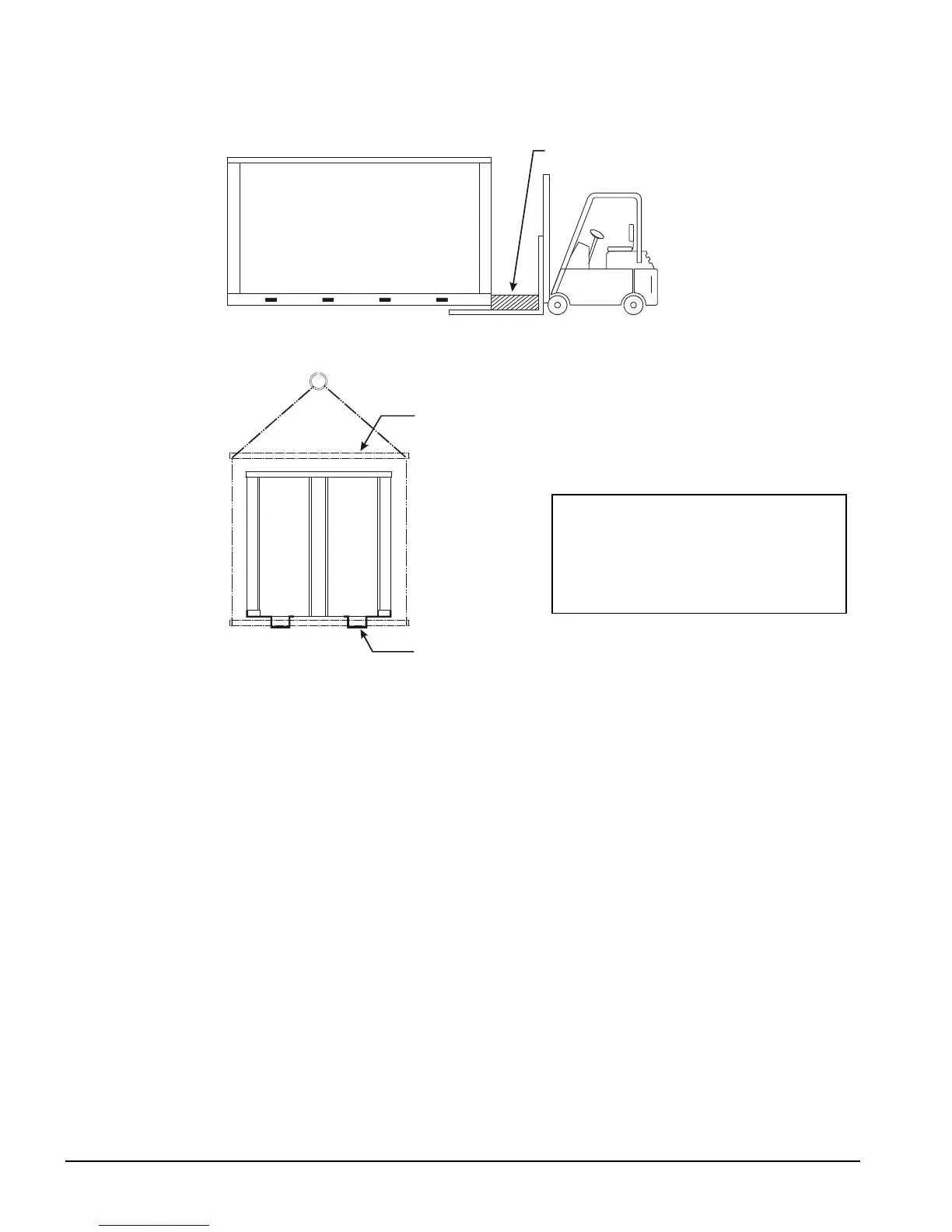
Figure 1, Suggested Pushing Arrangement
Figure 2, Suggested Lifting Arrangement
Location
Unit Placement
AGZ units are for outdoor applications and can be mounted on a roof or at ground level.
Set units on a solid and level foundation. For roof-mounted applications, install the unit on
a steel channel or I-beam frame to support the unit above the roof. For ground level
applications, install the unit on a substantial base that will not settle. A one-piece concrete
slab with footings extended below the frost line is recommended. Be sure the foundation is
level (within 1/2” [13 mm] over its length and width). The foundation must support the
operating weights listed in the Physical Data Tables on pages 16 and 17. It is recommended
that the unit be raised a few inches with a suitable support, located at least under the
mounting locations, to allow water to drain from under the unit and to facilitate cleaning
under it.
Since its operation is affected by wind, the unit should be located so that its length is
parallel with the prevailing wind. If this is not practical, use field fabricated wind
deflectors.
Service Access
Each end of the unit must be accessible after installation for periodic service. Compressors,
filter-driers, and liquid line solenoid valve are accessible from the end of the unit. High-
pressure, low-pressure, and motor protector controls are on the compressor. Most
operating, equipment protection, and starting controls are located in the unit control box.
NOTE:: The fork lift slots can be used for
lifting by inserting sufficiently strong pipe
through them as shown in Figure 2.
Use the outboard slots on three-fan units
and the only two on two-fan units.

 Loading...


