IOMM AGZB1 AGZ 010B through 034B 39
Events (Limit Alarms)
The following events limit the operation of the chiller in some way as described in the
Action Taken column. These alarms are auto-clearing based on reaching the conditions in
the reset column.
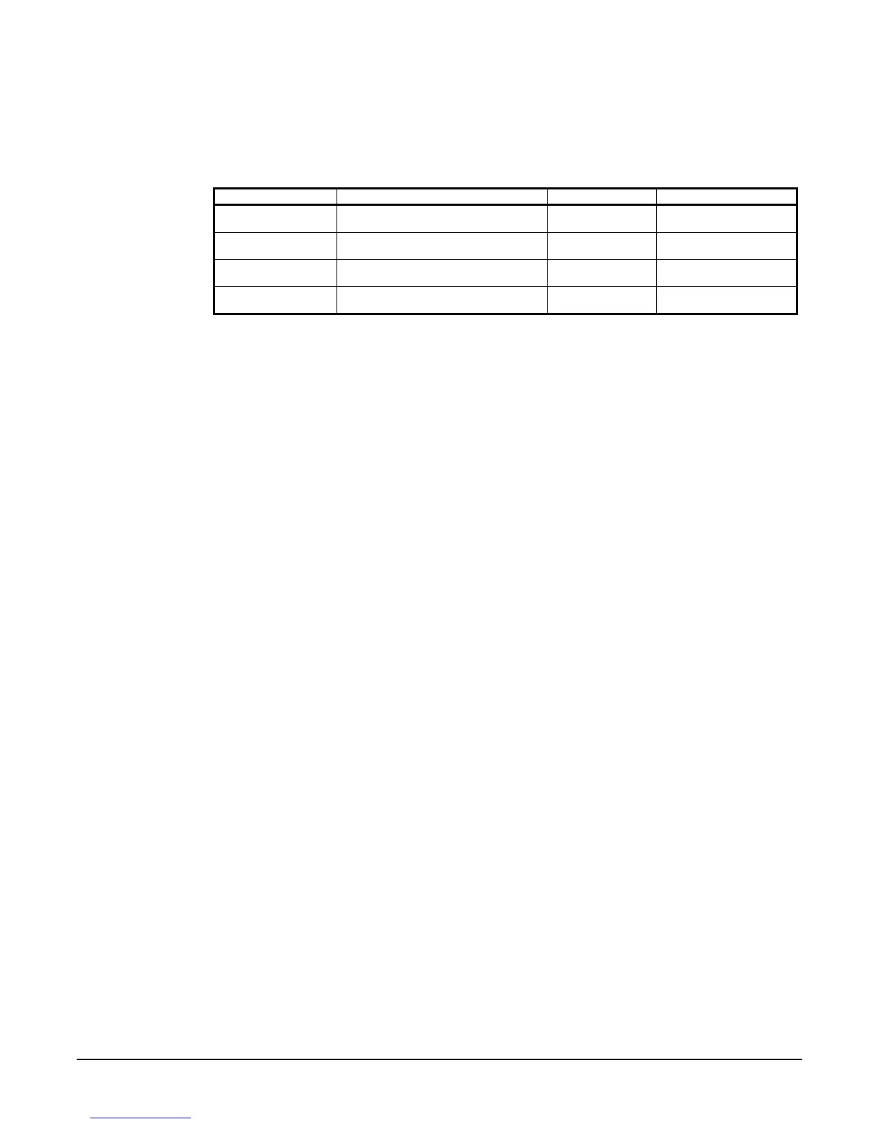
Table 21, Events (Limit Alarms)
Description Occurs When: Action Taken Reset
Condenser Pressure
High Unload
Pressure > High Condenser Stage
Down setpoint
Shutoff Stage #2
Condenser Press drops
below (SP – 100psi)
Failed Pumpdown
Unit is pumping down for over 60
seconds
Shut down unit N/A
Low Evaporator
Pressure – Hold
Pressure < Low Evap Pressure–Hold
setpoint
Hold @
Stage 1
Evap Press rises above
(SP + 8psi)
Low Evaporator
Pressure – Unload
Pressure < Low Evap Pressure–
Unload setpoint
Shutoff
Stage 2
Evap Press rises above
(SP + 10 psi)
NOTE: SP = Setpoint
Control Functions and Definitions
Control Band
Control Band = Evap delta setpoint * 0.6
Upper and Lower Control Band
The control band is normally centered around the active LWT setpoint. If the chiller is not
set up to use glycol, then the control band will be shifted up relative to the LWT setpoint to
keep the lower end of the control band at least at 39°F. If the band doesn’t need to be
shifted to achieve this, it will remain centered on the active LWT setpoint.
In the staging logic, an upper and lower control band are used. The lower control band is
calculated as follows:
IF Active LWT Setpoint – 39 < 0.5 * Control Band THEN
Lower Control Band = Active LWT Setpoint – 39
ELSE Lower Control Band = 0.5 * Control Band
The upper control band is then Control Band – Lower Control Band
Leaving Water Reset
The leaving water reset input uses a 4-20mA signal to reset the leaving water setpoint to a
higher value. The adjustment varies linearly from 0 to 10°F, with a reset of 0 for a 4mA
signal and a reset of 10 for a 20mA signal.
Active LWT Setpoint
The active LWT setpoint represents the current control setpoint based on unit mode and
reset. If unit mode is ice, then the active setpoint is equal to the ice setpoint. If the unit
mode is cool, the active setpoint is the cool setpoint plus the leaving water reset value.
LWT Error
LWT error compares the actual LWT to the active LWT setpoint. The equation is:
LWT error = LWT – active LWT setpoint
LWT Slope
LWT slope is calculated such that the slope represents a time frame of one minute.

 Loading...


