IOMM AGZB1 AGZ 010B through 034B 35
Inputs/Outputs
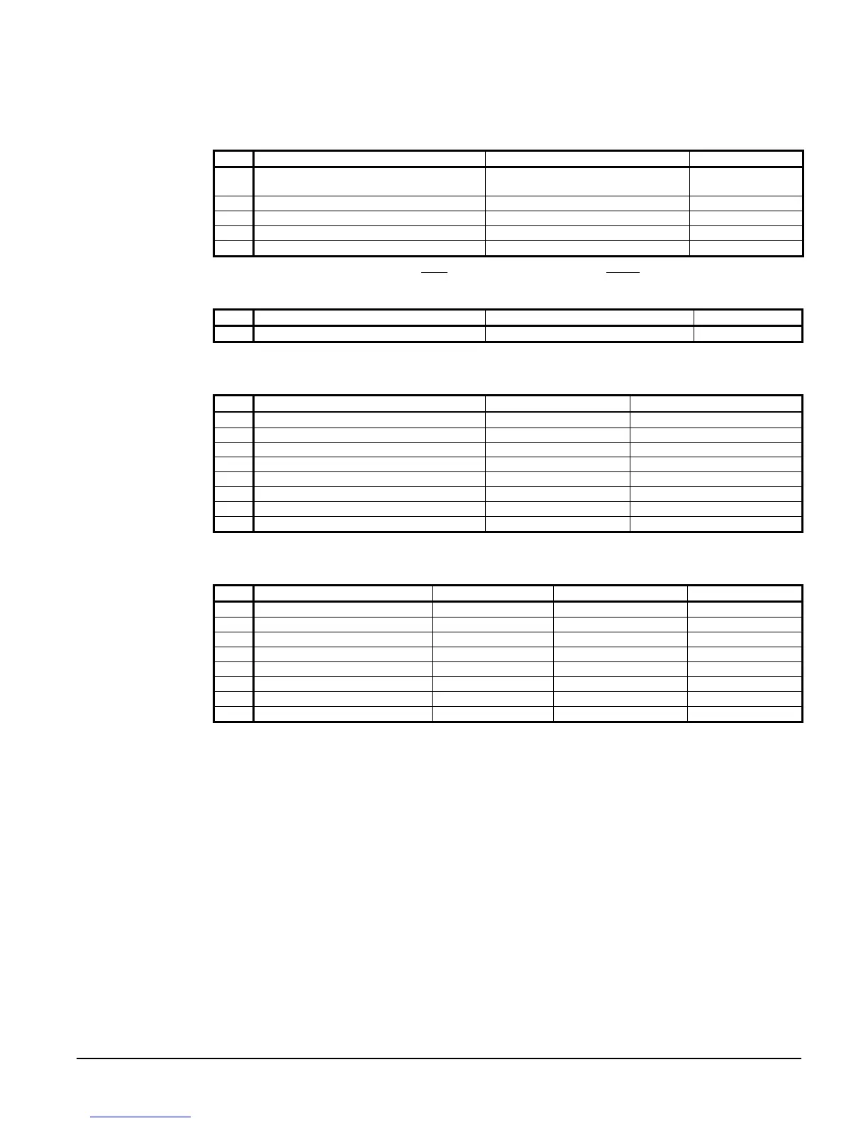
Table 18, Inputs and Outputs
Analog Inputs
# Description Signal Source Range
1 Reset of Leaving Water Temperature 4-20 mA Current
0 to10 degrees
60°F max inlet
2 Evaporator Refrigerant Pressure 0.5 to 4.5 VDC (NOTE 1)
0 to 132 psi
3 Condenser Refrigerant Pressure 0.5 to 4.5 VDC (NOTE 1)
3.6 to 410 psi
4 Leaving Evaporator Water Temperature
Thermister (10k at 77°F, 25°C)
-58 to 212°F
5 Outside Ambient Temperature
Thermister (10k at 77°F, 25°C)
-58 to 212°F
NOTE 1: Value at the converter board input. Value at the converter board output is 0.1 VDC – 0.9 VDC.
Analog Outputs
# Description Output Signal Range
1-4 None -- --
Digital Inputs
# Description Signal Signal
1 Unit OFF Switch 0 VAC (Stop) 24 VAC (Auto)
2 Remote Start/Stop 0 VAC (Stop) 24 VAC (Start)
3 Evaporator Water Flow Switch 0 VAC (No Flow) 24 VAC (Flow)
4 Motor Protection 0 VAC (Fault) 24 VAC (No Fault)
5 Ice Mode Switch 0 VAC (Normal) 24 VAC (Ice)
6 Phase Voltage Fault 0 VAC (Fault) 24 VAC (No Fault)
7 Open -- --
8 Open -- --
Digital Outputs
# Description Load Output OFF Output ON
1 Alarm Alarm Indicator Alarm OFF Alarm ON
2 Evaporator Water Pump Pump Contactor Pump OFF Pump ON
3 Liquid Line Solenoid Cooling OFF Cooling ON
4 Motor Control Relay #1 Starter Compressor OFF Compressor ON
5 Motor Control Relay #2 Starter Compressor OFF Compressor ON
6 Condenser Fan #1 Fan Contactor Fan OFF Fan ON
7 Condenser Fan #2 Fan Contactor Fan OFF Fan ON
8 Condenser Fan #3 Fan Contactor Fan OFF Fan ON
Setpoints
The setpoints shown in Table 19 are battery-backed and remembered during power off, are
factory set to the Default value, and can be adjusted within the value shown in the Range
column.
The PW (password) column indicates the password level that must be entered in order to
change the setpoint. Passwords are as follows:
O = Operator [0100]
M = Manager, [2001] M level settings are not normally changed for chilled water air-
conditioning applications.

 Loading...


