IOMM AGZB1 AGZ 010B through 034B 43
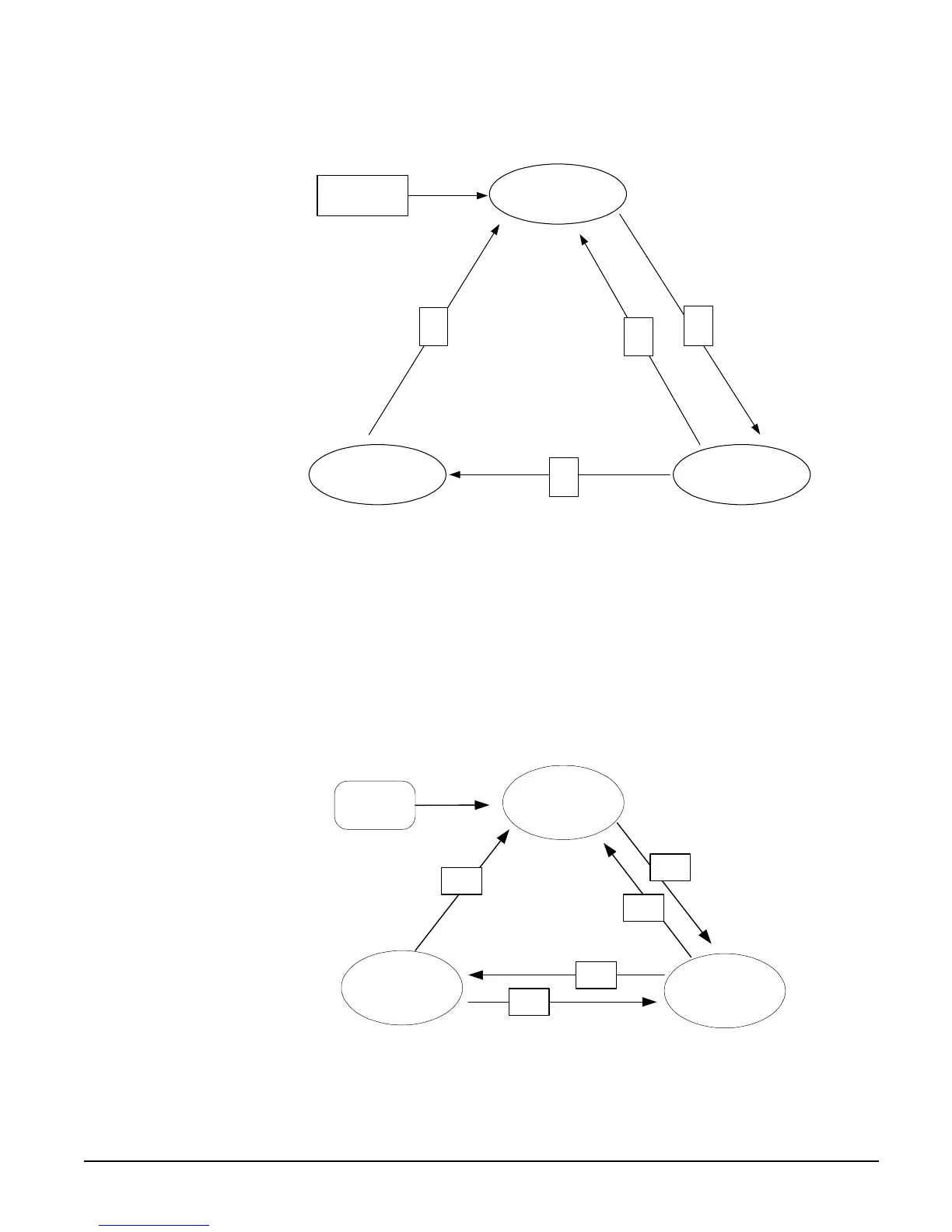
Figure 13, Unit State Diagram
Off
Pumpdown Auto
T1
T4
T3
T2
Power On
Unit State Diagram
Evaporator Water Pump State Control
Operation of the evaporator pump is controlled by the state-transition diagram shown
below.
Figure 14, Evaporator Pump State
Power ON
OFF
RUN
START
T1
T4
T2
T3
Evaporator Pump
States
T5
See transition code on following page.

 Loading...


