1-9
IM-FCU-0999
NOTE:
• Avoid using the short duct on which the air discharge grille can be completely closed, to prevent evaporator freezing.
• In order to prevent condensation forming, be sure that there is sufficient thermal insulation and no leakage of cool air when
installing the short duct.
• Keep the introduction of fresh air intake within 20% of total air flow. Also provide a chamber and use a booster fan.
Sealing Material
• It is possible to seal one of the four air discharge outlet. (sealing two or more air discharge outlet could cause a malfunction)
• Remove the front panel and insert the sealing material into the air discharge outlet on the indoor unit to seal the air outlet.
• The sealing material is the same length as the longer air discharge outlet. If it is desired to seal the shorter air discharge
outlet, cut the sealing material to shorten it.
• Push the sealing material in about 10mm beyond the bottom surface of the indoor unit so that it does not touch the air louver.
Be sure not to push the sealing material in any farther than about 10mm.
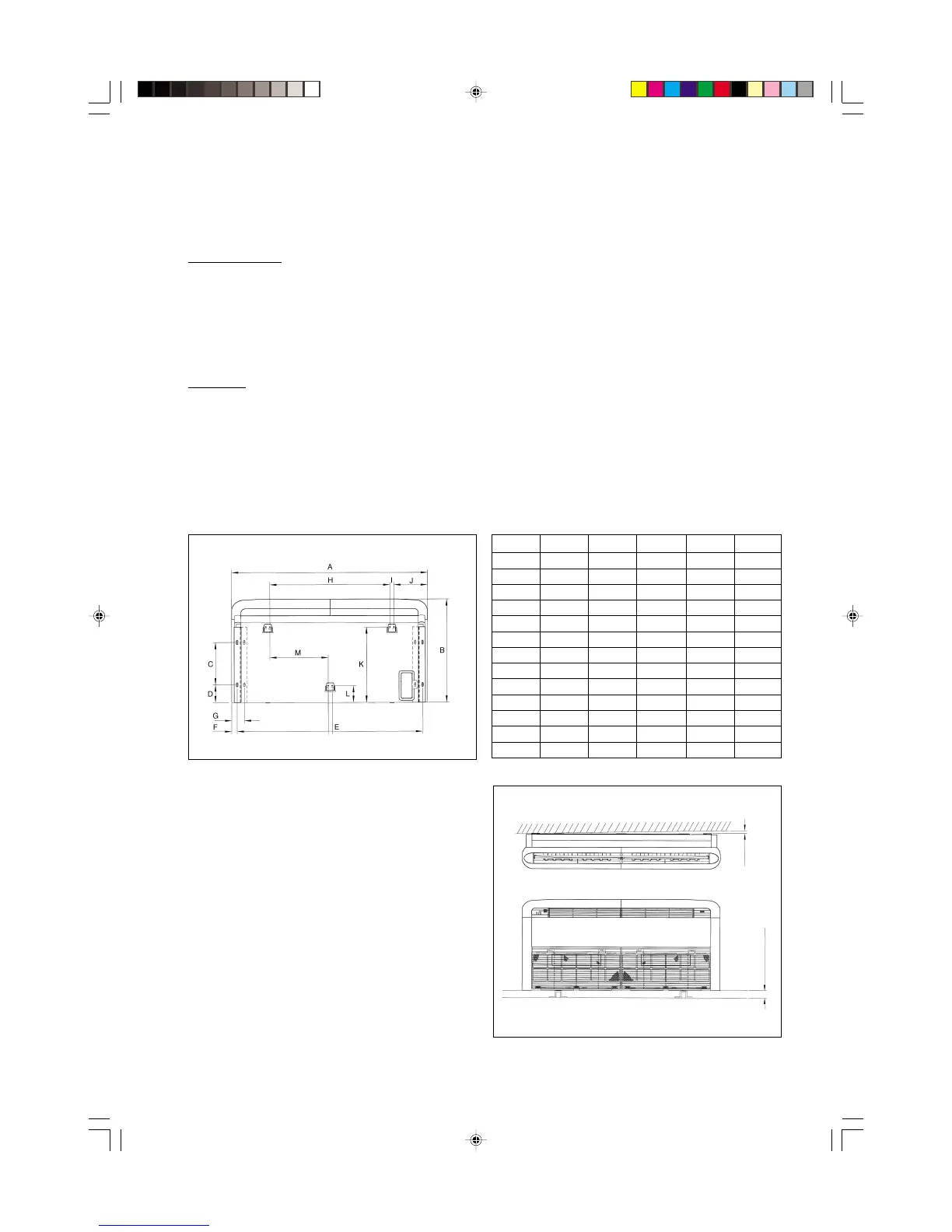
FIGURE A
CE Model
Preliminary Site Survey
* Electrical supply and installation shall conform to the local
authority (e.g. National Electrical Board).
* Voltage supply fluctuation must not exceed ±10% of the
rated voltage. Electricity supply lines must be
independent of welding transformers which can cause high
supply fluctuation.
* Ensure that the installation location is convenient for
wiring and piping.
Standard Mounting
Ensure that the overhead supports are strong enough to hold
the weight of the unit. Position the hanger rods (wall
mounting bracket for floor standing), and check for its
alignment with the unit as shown in Figure A. Also, check
that the hangers are secured and the base of the fan coil unit is
leveled in both horizontal directions, taking into account
the
gradient for drainage flow as recommended in Figure B.
MODEL
20 25 30 40 50
A 1214 1214 1214 1714 1714
B 666 666 666 666 666
C 273 273 273 273 273
D 130 130 130 130 130
E 1160 1160 1160 1560 1560
F 27 27 27 27 27
G 77 77 77 77 77
H 745 745 745 1235 1235
I 25 25 25 25 25
J 209 209 209 331 331
K 486 486 486 486 486
L 108 108 108 108 108
M 360 360 360 600 600
FIGURE B
Please ensure that the following steps are taken:
* Check the gradient for drainage flow as recommended in
Figure B.
* Provide clearance for easy servicing and optimal air flow
as shown in Figure C.
* The indoor unit must be installed such that there is no short
circuit of the cool discharge air with the warm
return air.
* Do not install the indoor unit where there is direct
sunlight shining on the unit. The location should be
suitable for piping and drainage installation. The unit must
be a large distance away from the door.
10.0mm
10.0mm lower
IM-FCU-0999L (Eng) 7/14/00, 1:18 PM9
 Loading...