1-5
IM-FCU-0999
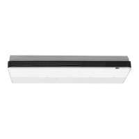
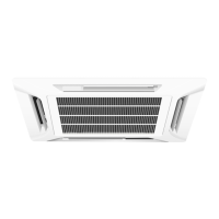
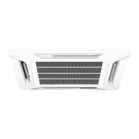
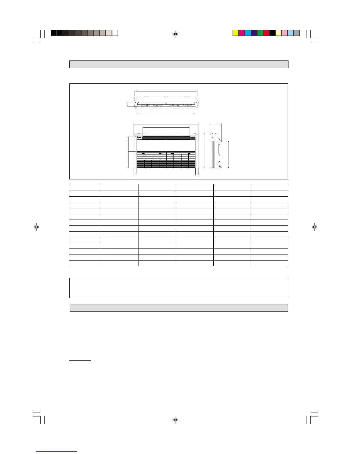
OUTLINE AND DIMENSIONS
INDOOR UNIT (CE SERIES)
MODEL 20DW 25DW 30DW 40DW 50DW
A 1174 1174 1174 1674 1674
B 75 75 75 75 75
C 1082 1082 1082 1582 1582
D 68 68 68 68 68
E 58 58 93 93 93
F 156 156 156 156 156
G 1214 1214 1214 1714 1714
H 57 57 57 57 57
I 670 670 670 670 670
J 216 216 216 216 216
K 319 319 319 319 319
L 879 879 879 1379 1379
M 517 517 517 517 517
All dimensions are in mm.
! Caution
Sharp edges and coil surfaces are potential locations which may cause injury
hazards. Avoid from being in contact with these places.
A
B
C
G
L
F
E
M
I
H
H
KJ
D
• Electrical supply and installation is to conform to local authority's (e.g. National Electrical Board) codes and regulations.
• Voltage supply fluctuation must not exceed ±10% of rated voltage. Electricity supply lines must be independent of welding
transformers which can cause high supply fluctuation.
• Ensure that the location is convenient for wiring, piping and drainage.
• The indoor unit must be installed in such a way that is free from any obstacles in the path of cool air discharge and warm air
return, and must allow spreading of air throughout the room (near the center of the room).
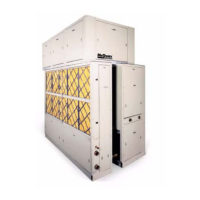
CC Model
• Use the hanger supplied with the unit.
• Make sure that the wall is sufficiently strong to withstand
the weight.
Provide clearance for servicing ease and optimal air flow as
shown in the diagram.
INSTALLATION OF INDOOR UNIT
IM-FCU-0999L (Eng) 7/14/00, 1:18 PM5
 Loading...