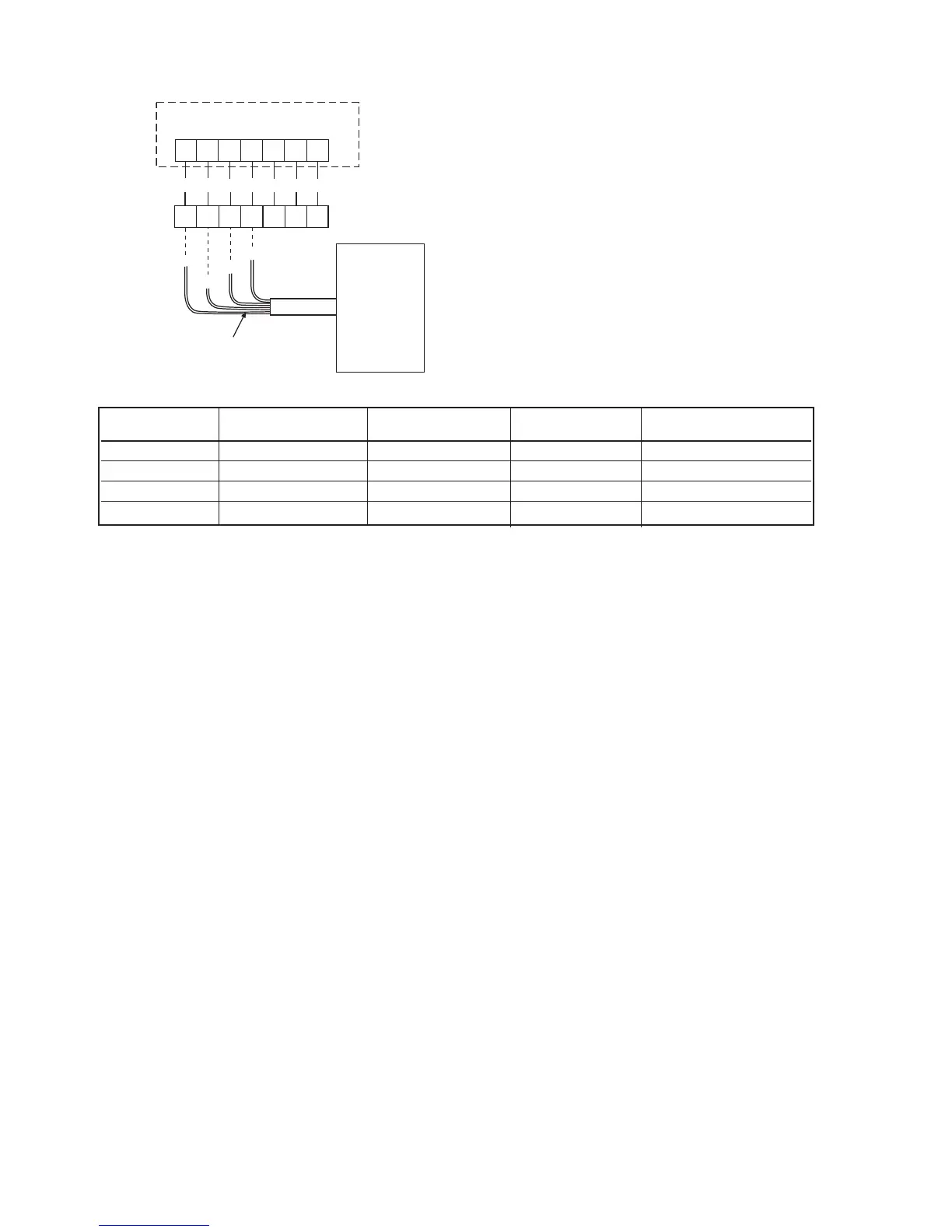
MicroTech Wall Sensor – Wiring Diagram
Sensor Tenant Override Setpoint Bi-Metal No. of Conductors
Part No. Switch Adjustment Pot Thermometer Required
107230301 Yes No No 4 + Shield
107230401 Yes No Yes 4 + Shield
107230501 Yes Yes No 4 + Shield
107230601 Yes Yes Yes 4 + Shield
MicroTech Controller
J2
6 7 8 9 10 11 12
62 63 64 65 66 67 68
1 2 3 4 5 6 7
Terminal Board #1
Red
Grn
Wht
Blk
Stranded Wire
(Blk, Wht, Grn, Red)
Wall Sensor
Locate the sensor on a wall where exposure to unrestrict-
ed air circulation represents the average temperature of
the space. A common mistake is to mount the sensor too
close to the supply air diffuser in a room. This causes short
cycling of the air conditioning unit and large room tempera-
ture swings.
Note:
All sensors have black (common), white (thermistor), and
red (LED) wires. With the tenant override and /or set point
adjustment option, a green wire is provided. The optional
thermometer does not affect wiring.
Refer to IM 529 for detailed installation instructions.
IM 742 / Page 17

 Loading...