Page 14 of 24 / IM 439
14-Position Terminal Strip
Pin Designation Description
1CTransformer ground (Ovac)
2RTransformer supply (24vac)
3V-DC power connection
4PPump request output
5A Alarm fault output
6UUnoccupied input
7LLoad shed input
8ERemote shutdown input
9F+DC power connection
10 Y1 Occupied cooling mode input
11 W1 Occupied heating mode input
12 G Fan only input
13 W2 Unoccupied heating mode input
14 O Tenant override input
Mark IV/AC Sequence of
Operation
The Mark IV/AC control board has built-in night setback
operation. A “grounded” signal to the “U” terminal on the low
voltage terminal strip puts the unit into the unoccupied mode
for night setback operation. The fan shuts off and the unit is put
under control from the night setback terminal on the thermo-
stat, W2 on single compressor and W3 on dual compressor
Ground
Unit
3
To
Additional
Units
Time
Clock
Unit
2
Unit
1
Unit Operation
General
Each unit has a printed circuit board control system. The low
voltage output from the low voltage terminal strip on the control
board is always 24 volts DC (direct current). Terminals C and
R on the low voltage terminal strip supply 24 volts AC power.
The unit has been designed for operation with a 24 volt
mercury bulb type wall thermostat or a microelectronic wall
thermostat selected by the manufacturer. Do not operate the
unit with any other type of wall thermostat.
Table 3.
LEDs
FAULT
INDICATION
Yellow Green Red
OUTPUT
Normal Mode Off On Off Off
High Pressure Fault Off Off Flash On
Low Temperature Fault* Flash Off Off On
Condensate Overflow On Dim Off On
Brown-out Off Flash Off On
Load Shed Off Off On Off
Unoccupied Mode On On Off Off
Unit Shutdown Off Flash Off On
*In heating mode only.
Mark IV/AC Control Units
Single compressor units have a single Mark IV/AC circuit
board and dual compressor units have two Mark IV/AC circuit
boards. The refrigerant circuits on dual compressor units
operate totally independent from each other and allow for
total independent operation of each circuit.
The Mark IV/AC circuit board has built-in features such as
random start, compressor time delay, night setback, load
shed, shutdown, condensate overflow protection, defrost
cycle, brownout, and LED/fault outputs.
The 24 volt low voltage terminal strip on each board is set
up so R-G energizes the fan, R-Y1 energizes the compressor
for cooling operation, R-W1 energizes the compressor and
reversing valve for heating operation. The reversing valve is
set up to be energized in the heating mode. The circuit board
has a fan interlock circuit to energize the fan whenever the
compressor is on if the thermostat logic fails to do so.
The Mark IV/AC control board has a lockout circuit to stop
compressor operation if any one of its safety switches opens
(high pressure switch and low pressure switch). If the low
temperature switch opens, the unit will go into the cooling
mode for 60 seconds to defrost any slush in the water-to-
refrigerant heat exchanger. After 60 seconds the compressor
is locked out. If the condensate sensor detects a filled drain
pan, the compressor operation will be suspended only in the
cooling mode. The unit is reset by opening and closing the
disconnect switch on the main power supply to the unit in the
event the unit compressor operation has been suspended
due to low temperature (freezestat) switch, high pressure
switch or low pressure switch. The unit does not have to be
reset on a condensate overflow detection.
The Mark IV/AC control board has a fault output signal to
an LED on a wall thermostat. Table 3 shows for which functions
the fault output is “on” (sending a signal to the LED).
units; day heating and cooling operation is locked out. R-W2
energizes the compressor and reversing valve for heating
operation. Night setback operation can be overridden for two
hours by toggling the fan switch (intermittently closing the R
to O terminals) on the Deluxe Auto Changeover thermostat.
Day thermostat setpoints then control the heating and cool-
ing operation. The Mark IV/AC control system is also set up
for load shed and shutdown operation on receipt of a
“grounded” signal to the “L” and “E” terminals, respectively,
on the low voltage terminal strip (see Figure 16).
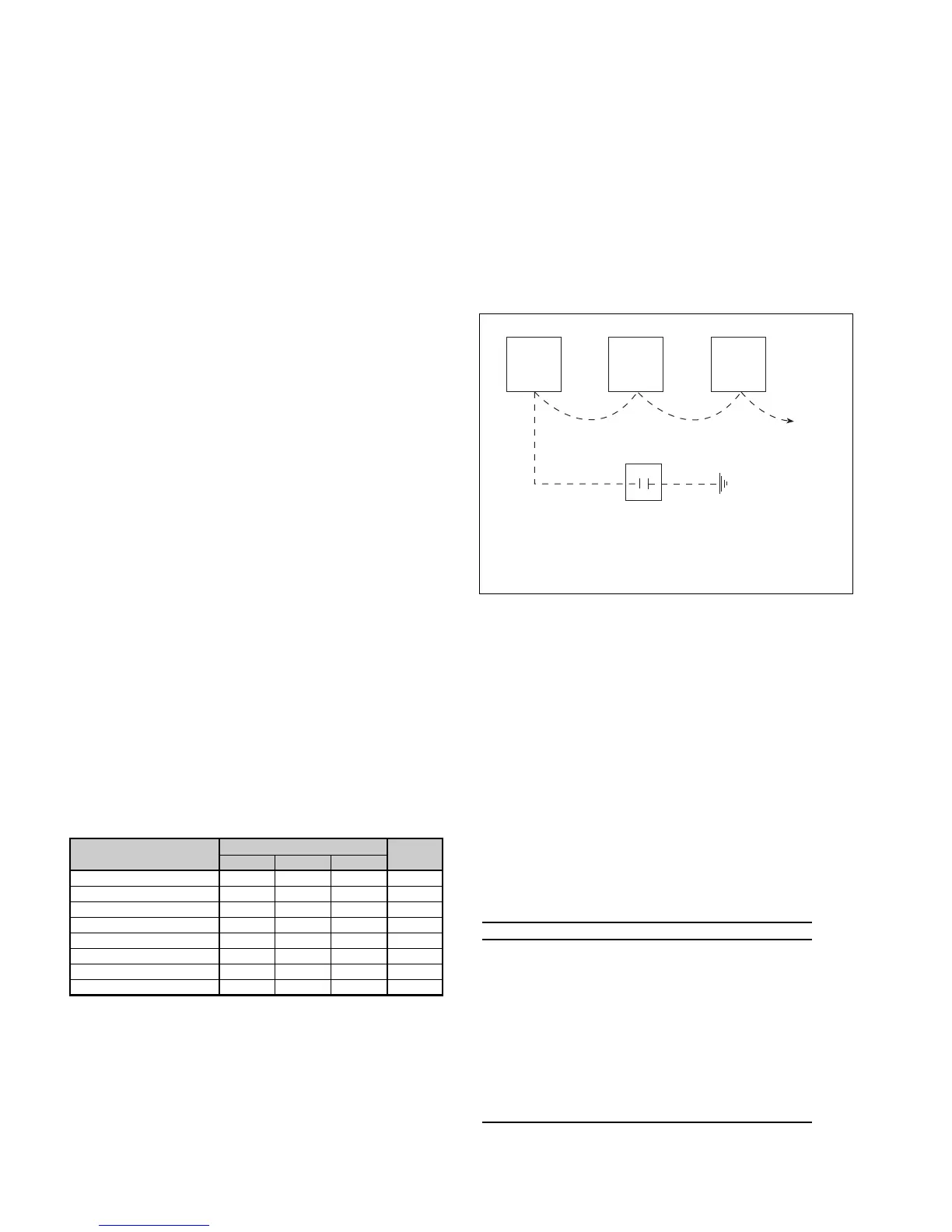
Figure 16.
To activate the unoccupied mode for units on the same clock schedule,
a single wire can be “daisy chained” between units and simply grounded
through the timeclock contacts. The same system can also be done to
activate the load shed and emergency shutdown modes by running
additional wires between units to ground.
The P and C terminals of the Mark IV/AC board are used
for pump restart. These terminals pass a voltage signal
whenever the unit’s compressor is turned on. This signal is
detected by a Pump Restart Relay board (P/N 898-613703X01)
providing a N.O. or N.C. set of contacts for heat pump loop
circulation pump control. When used with the Loop Water
Controller, the relay operation accommodates turning off
circulation pumps during unoccupied periods with a safety
override dependent on, at minimum, one WSHPs need. The
P and C terminals may be “daisy chained” between 200 units
(see page 18).