-41-
Design & installation Guide For McQuay MDS Multi System
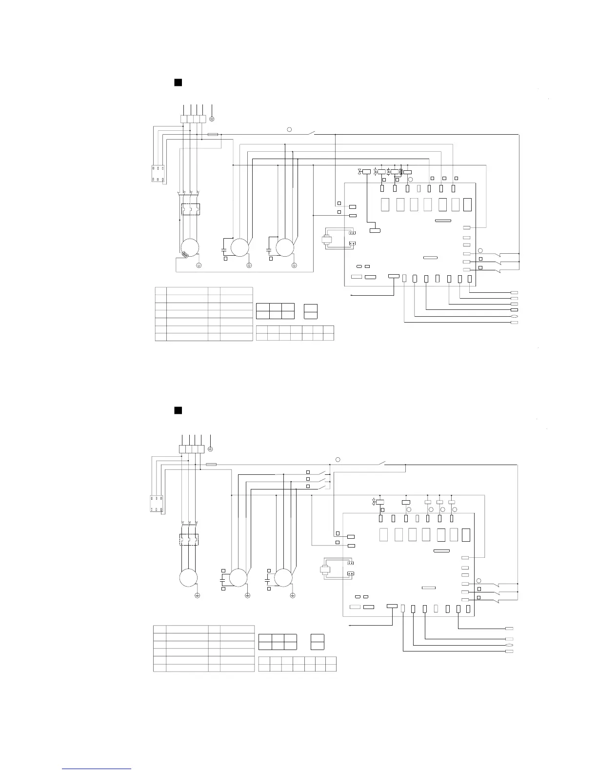
Model MDS050AR(380V/3N~/50Hz)
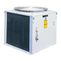
Model MDS060A
BGND
A
AI-IN
McQuay
HP
LP
OV-COMP1
OV-COMP2
OV-COMP3
NEUTRAL
NEUTRAL
LIVE
RC
C1
JP2JP1
J2
J1
RY7
RY6RY4 RY5
RY3RY1 RY2
MidLet
OutLet
RTN
C-BTM
LOW-FAN
MID-FAN
HI-FAN
DIG COMP
FIXED COMP
PWMV
4WV
TRAN-H
TRAN-L
InLet
OD TEMP.
CN1
DLT
HP
LP
C2
~
M
~
M
~
M
Connecting indoor
unit communication
Reverse phase-loss protector
Overload protector
Trans-
former
RC
OFF
ON
DIP switch J2 setting:
J2.6
OFF
J1.7J1.5
J1.4J1.3J1.2J1.1
J1.6
18
T2
T3T1
OL
23
22
21
20
1
2
L1
LPHP
OFF
71
81
EXV
16
15
L
12
N
3
DB3A
S
R
T
N
FU
81
N
KM
PWMV 4WV
71
R
DB3A
S
T
OFFOFF
DIP switch J1 settings:
OFF
OFF
OFFOFF
JP2JP1
12.9A
OL
KM
OL
FU
PWMV
EXV 4WV
DB3A
KM
C1-2 OL
Ambient temperature sensor(TH2)
Air discharge temperature sensor of the digital compressor(TH1)
Coil inlet temperature sensor(TH4)
Coil middle temperature sensor(TH5)
Coil outlet
temperature sensor(TH6)
Overload setting&Jumper settingsǖ
Four-way valve
Contactor
Capacitor
High pressure switch Low pressure switch
Description of components and parts:
Symbol DescriptionSymbol Description
Shaft
heater
Digital
compressor
red
red
Fan 1 Fan 2
Fuse
Electric expansion valve
Solenoid valve
Return air temperature sensor(TH3)
Surge suppressor
Notes:
1:
-----------
Field wiring
2:
--------------
Factory wiring
3: J2.1~2.5 sets the internetworking control address
4: If the unit connected at the end of the bus,JP1,JP2 is on.
yellow
green
red
yellow
green
red
blue
brown
yellow
orange
blue
brown
yellow
orange
HP
LP
OV-COMP1
OV-COMP2
OV-COMP3
NEUTRAL
McQuay
B GND
A
AI-IN
NEUTRAL
LIVE
C1
JP2JP1
J2
J1
RY7
RY6RY4 RY5
RY3RY1 RY2
MidLet
OutLet
RTN
C-BTM
LOW-FAN
MID-FAN
HI-FAN
DIG COMP
FIXED COMP
PWMV
4WV
TRAN-H
TRAN-L
InLet
OD TEMP.
DLT
HP
LP
C2
~
M
~
M
~
M
Digital
compressor
Fan 1 Fan 2
Trans-
former
white
black
white
black
Connecting indoor
unit communication
Ambient temperature sensor(TH2)
Air discharge temperature sensor of the digital compressor(TH1)
Coil middle
temperature sensor(TH5)
red
blue
brown
orange
red
blue
brown
orange
yellow
green
red
yellow
green
red
DIP switch J2 setting:
J2.6
ON
J1.7J1.5
J1.4J1.3J1.2J1.1
J1.6
17
18
19
T2
T3T1
OL
23
22
21
20
1
L1
LP
HP
K1-3
K1
K2
K3
K3K2K1
OFFON
OFF
71
81
16
15
L
12
N
8
7
5
3
DB3A
SRT
N
380V/3N~/50Hz
FU
81
N
KM
PWMV
71 R
DB3A
S
T
OFFOFF
DIP switch J1 settings:
OFF
OFF
JP2JP1
OFF OFF
14.0A
OL
Overload setting&Jumper settings:
KM
OL
FU
PWMV
DB3A
KM
C1-2 OL
Description of components and parts:
Symbol DescriptionSymbol Description
Reverse phase-loss protector
Contactor
Capacitor
High pressure switch
Overload protector
Low pressure switchRelay
Fuse
Return air temperature sensor(TH3)
Notes:
1:
-----------
Field wiring
2:
--------------
Factory wiring
3: J2.1~2.5 sets the internetworking control address
4: If the unit connected at the end of the bus,JP1,JP2 is on.
Solenoid valve