-44-
Design & installation Guide For McQuay MDS Multi System
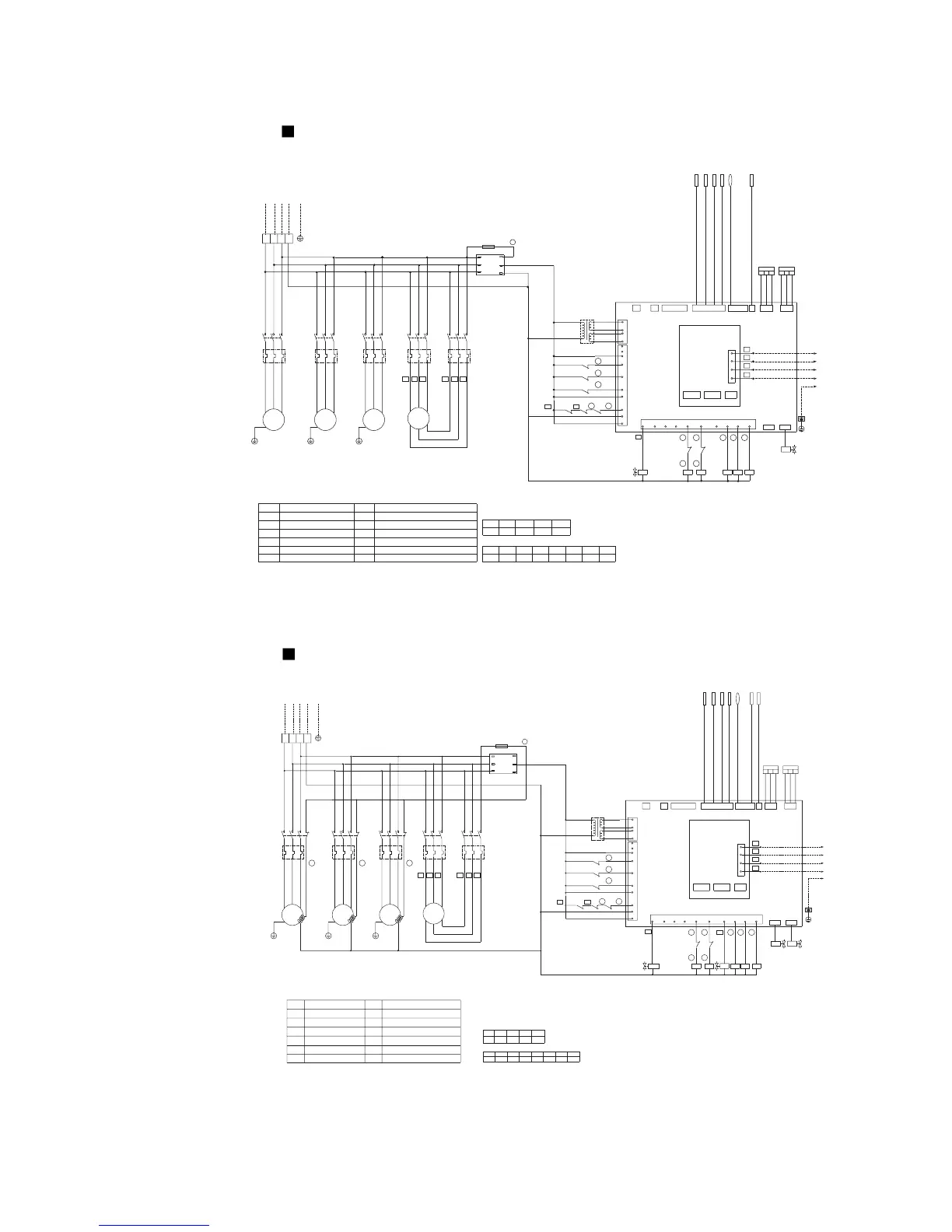
Model MDS150B
Model MDS150BR
23
HPT
3121
LPT
HI-U
LOW-U
AinApcBpc Bin
S2 S3S1
MDS-M
~
M
MDS-P
~
M
~
M
M
~
Air discharge temperature
sensor of the digital compressor TH1
RED
BLACK
WHITE
RED
BLACK
WHITE
Air suction temperature sensor TH12
Over cooling circuit outlet temperature sensorTH11
After over cooling circuit temperature sensor TH10
Before over cooling circuit temperature sensor TH9
Ambient temperature sensor TH8
Connecting the indoor unit
Connecting central control system
30
31
32
33
8
KM2
12
OL2
T3
OL3
KM3
T2
T1
17
DB3A
5
FIX3-OL
DIG
FIX1
FIX2
TH7 TH5
KM4 KM5
TH1TH2
EXV4
EXV1
EXV4
L
T
71
FU
TH8TH10TH9TH11TH12TH6
HI-1
TH3
V1+
TR
V2-
V2+
V1-
DIG-OL
13
14
OL1
OL3
FIX2-OL
FIX1-OL
LOW-I
4WV
FANL
FANH
24
SV2
PMW
11
10
1
SV1
KM5 KM4 KM1
PMW
KM3
3
HP
N
L
OL5
J1
16
15
OL4
HP
J18
LP
R
N
24 25 26
KM4
OL4
2321 22
OL5
KM5
T3
T1
T2
L1
S
81
TH4
N
TS
380V/3N~/50Hz
R
KM1
OL1
T3
T2
T1
OL2
KM2
HPT
TR
FUDB3A
PMW
OL
HP
LPT
KM EXV4
Description of components and parts :
Symbol Description Symbol Description
Phase-loss/reverse protector Fuse
Contactor
High-pressure switch
Low -pressure sensor
High-pressure sensor
Transformer
Overload protector
Solenoid valve
Over cooling electronic expansion valve 4
3.3A 1.8A
OL4 OL5
14.0
OL3OL2
14.014.0
OL1
Overload protection settings :
ONON
S3.4
OFF
S3.2S2.3
ONON OFF
S3.1 S3.3S1.1
OFF
S1.2
OFF
S2.2
DIP switch settings :
Constant-speed
compressor 1
Constant-speed
compressor 2
Digital compressor Fan motor
BLUE
YELLOW
RED
BLUE
YELLOW
RED
BLUE
YELLOW
RED
BLUE
YELLOW
RED
BLACK
WHITE
BROWN
YELLOW
BLUE
RED
BLACK
WHITE
Notes:
1:
-----------
Field wiring
2:
--------------
Factory wiring
3: S1.3~S1.8 set the number of indoor units. S2.1 sets the
unit as a master/slave. For details of S2.4~S2.8.
~
M
Bin AinApcBpc
MDS-M
MDS-P
S3S1 S2
~
M
~
M
M
~
3
HPT
212
3
1
LPT
33
32
31
7
30
HPT
8
KM2
12
OL2
20
T3
OL3
KM3
T2
T1
17
TR
DB3A
5
FIX3-OL
DIG
FIX1
FIX2
TH7 TH5
4WV
KM4 KM5
HI-U
TH1
TH2
LOW-U
EXV4EXV1
EXV4
EXV1
L
T
71
FU
TH8TH10
TH9TH11
TH12
TH6
HI-1
TH3
V1+
TR
V2-
V2+
V1-
DIG-OL
13
14
OL1
OL3
FIX2-OL
FIX1-OL
LOW-I
4WV
FANL
FANH
24
SV2
PMW
11
10
1
SV1
KM5
KM4
KM1
PMW
KM3
3
HP
N
L
OL5
J1
16
15
OL4HP
J18
LP
R
N
24 25 26
KM4
OL4
2321 22
19
OL5
KM5
T3
T1
T2
L1
S81
TH4
14.0
OL3
1.8A
OL4
14.0
OL1
14.0
OL2 OL5
3.3A
S3.4
ON
S3.2
OFF
S2.3
ON OFF
S3.1 S3.3
ON
S1.1
OFF
S1.2
OFF OFF
S2.2
N
T
S
380V/3N~/50Hz
R
18
KM1
OL1
T3
T2
FU
EXV14WV
DB3A
T1
PMW
OL
HP
LPT
KM EXV4
OL2
KM2
Air suction temperature sensor TH12
Over cooling circuit outlet temperature sensorTH11
After over cooling circuit temperature sensor TH10
Before over cooling circuit temperature sensor TH9
Ambient temperature sensor TH8
Air discharge temperature sensor of the digital compressor TH1
BLACK
WHITE
BLACK
WHITE
BROWN
YELLOW
BLUE
RED
BLUE
YELLOW
RED
BLUE
YELLOW
RED
BLUE
YELLOW
RED
BLUE
YELLOW
RED
Connecting the indoor unit
Connecting central control system
Shaft heater
Shaft heater
Shaft heater
Constant-speed
compressor 1
Constant-speed
compressor 2
Digital compressor
Fan motor
Symbol
Description
Symbol Description
Phase-loss/reverse protector
System electronic expansion valve 1
Fuse
Four-way valve
Contactor
High-pressure switch
Low -pressure sensor
High-pressure sensor Transformer
Overload protector
Solenoid valve
Over cooling electronic expansion valve 4
Overload protection settings :
DIP switch settings :
Description of components and parts :
Coil inlet temperature sensor TH2
Notes:
1:
-----------
Field wiring
2:
--------------
Factory wiring
3: S1.3~S1.8 set the number of indoor units. S2.1 sets the
unit as a master/slave. For details of S2.4~S2.8.
RED
BLACK
WHITE
RED
BLACK
WHITE
 Loading...