-50-
Design & installation Guide For McQuay MDS Multi System
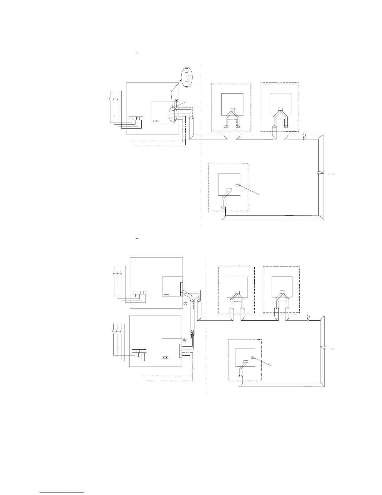
2.7.3 MDS080 240B/BR
BA
B
A
J2
BA
B
in
A
pc
A
in
B
pc
Connecting central control(optional)
B
in
A
pc
AB
pc
R
S
T
N
QF
L1 L2 L3 N
380V/3N~/50Hz
Communication wire
Communication wire
Indoor unit 1 Indoor unit 2
Indoor unit 3
Indoor unit i
Shielded wire
Main board
Communic-
ation port
Unit electric control box
Outdoor Indoor
Main board
Communic-
ation port
Main board
Communic-
ation port
Main board
Communic-
ation port
Communication wire
Main power
terminal support
The communication cable at the end of
indoor unit J2-1 needs to be set to ON.
Te
rm
in
a
l a
m
plifie
d figu
re
2.7.4 MDS260 300B/BR
Slave unit
AB
AB
in
B
in
A
pc
AB
pc
Master unit
in
B
in
A
pc
AB
pc
R
S
T
N
QF
L1 L2 L3 N
380V/3N~/50Hz
R
S
T
N
QF
L1 L2 L3 N
380V/3N~/50Hz
B
A
J2
Indoor unit 1
Indoor unit i
Indoor unit 2
Main board
Communic-
ation port
Main board
Communic-
ation port
Main board
Communic-
ation port
Outdoor
Outdoor
Indoor
Unit electric control box
Main board
Communic-
ation port
Main board
Communic-
ation port
Main power
terminal support
Connecting central control(optional)
Unit electric control box
Main power
terminal support
Communication wire Communication wire
Communication wire
Communication wire
The communication cable at the end of
indoor unit J2-1 needs to be set to ON.
 Loading...