Page 10 / IM 447
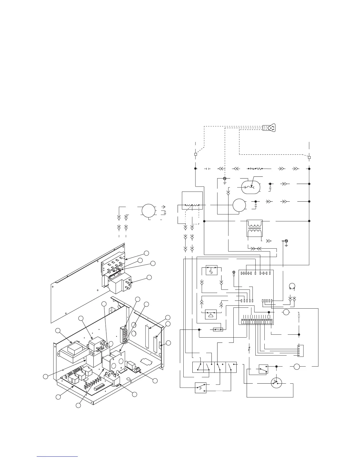
50 Hertz Mark IV MCO Boilerless Constant Fan
10
55
9
3
2
1
16
13
12
14
15
17
6
4
11
7
8
Fan
Motor
(size
004-010)
Optional Cordset
L1
L2
Ribbed Lead
Common
Compressor
Capacitor
Capacitor
Transformer
R
S
BK
TB
TB
OR2
Terminal Board 2
MCO
4-Button
Switch
H
L1
HI
BK RD
L2 L3
LO
W
2
1
3
MCO Thermostat
OR1
BL1
OR
11
C
RD1
BK1
BL2
OR11
WH1
Stop/Start Switch
HI Press
BR
BR
HP HP LT LT COF
BR1
WH2
BK3
OR12
OR4
S
RV RV V C
C
o
m
p
L1
Common
Fan
Mark IV
PC Board
RD3
BK3
LO Temp
BK2
OR4
WH3
Condensate
Sensor
BK5
BK4
BK1
BK1
RD1
Splice Connector
BK1
(004-006)
OR
BK
24VAC
WH
BR2 BR2
WH1
WH2
WH3
BR1 BR3
BL
BK10
(Not used on all sizes)
(Heat Pump Only)
Reversing
Valve
Solenoid
GN/YE
BK12
BR
R
BK11
BR
BK1
BK1
(008-010)
Fan
Motor
(size
013-016)
RD1 BK1
RD (013)
OR (016)
BL (013)
BK (016)
Cap
WH
BR
BR
GN/YE
BK
Resistor
(size 004-010 only)
BR
BR
GN/YE
GN/YE
BL 230V 50 Hz
GN/YE
YE
Limit
Switch
Heater
BL3 BL2 BL1OR3OR2OR1RD4
HR
BK1
BK2
W
2
OG
W
1
FELUAPV C
R
OR9
C
P
U
L
E
HR
Y
1
GR9
BL9
GY9
WH9
2
1
3
Boilerless
Thermostat
Standby Electric
Heat Switch
BR
BR
BR
BR
BR4
OR9
BR4
OR14
WH4
OR13
RD1 BK1
OR9
BR5
OR15
RD1
RD1
RD
(008)
RD1
BL70
BL70
WH5
BR
BL5
RD
RD
BK
Notes
1. Terminal block on PC board
provides 24 VAC at terminals
C and R. All other terminals are
24 VDC output.
2. All temperature and pressure
switches are normally closed.
3. Component layout is typical,
some components shown may
not be used.
4. Field supplied relays installed
on the unit terminals W1, W2,
Y1, Y2 and G may introduce
electrical noise. Never install
relay coils in series with the
inputs.
Component Layout
1. Tap-Touch Switch
2. Thermostat
3. Terminal Block
4. PC Board
5. Transformer
6. Boilerless Relay
7. Shutdown Relay
8. Auxiliary Relay
9. Heater Relay
10. Water Reg Valve Relay
11. Low Limit Thermostat
12. Night Setback Thermostat
13. Override Switch
14. Terminal Board 1
15. Terminal Board 2
16. Stop/Start Switch
17. Standby Electric Heat Switch
>> Plug Connection
TB Terminal Block
ACO Automatic Change Over
MCO Manual Change Over
BR Boilerless Relay
HR Heater Relay
Typical Wiring Diagrams for
Units with Mark IV/AC Controls
 Loading...