48 WGS 130A to 190A OM WGS-5
Soft Load – (ON/OFF)
Begin Capacity Limit – (Unit %)
Soft Load Ramp – (seconds)
The Soft Load Unit Limit increases linearly from the Begin Capacity Limit setpoint to
100% over the amount of time specified by the Soft Load Ramp setpoint. If the option is
turned off, the soft load limit is set to 100%.
Demand Limit
The maximum unit capacity can be limited by a 4 to 20 mA signal on the Demand Limit
analog input at the unit controller. This function is only enabled if the Demand Limit
setpoint is set to ON.
As the signal varies from 4 mA up to 20 mA, the maximum unit capacity changes linearly
from 100% to 0%. Although the demand limit can call for 0% capacity, this signal will
never cause a running compressor to shut down. Rather, all running compressors will be
held at minimum load, and this may occur at a demand limit value that is actually less than
20mA.
Network Limit
The maximum unit capacity can be limited by a network signal. This function is only
enabled if the unit control source is set to network. The signal will be received through the
BAS interface on the unit controller.
As the signal varies from 0% up to 100%, the maximum unit capacity changes linearly from
0% to 100%. Although the network limit can call for 0% capacity, this signal will never
cause a running compressor to shut down. Rather, all running compressors will be held at
minimum load, and this may occur at a network limit value that is actually less than more
than 0%.
Condenser Pump and Tower Control
Condenser pump and cooling tower control logic requires that the unit be configured as
water-cooled in order to be active. The unit controller controls water-cooled components
such as condenser pumps and tower controls, since there is usually one tower per unit. Air-
cooled equipment, associated with the remote condenser option, is controlled by the circuit
controllers. Remote evaporative condensers require a self-contained, on-board, discharge
pressure control system.
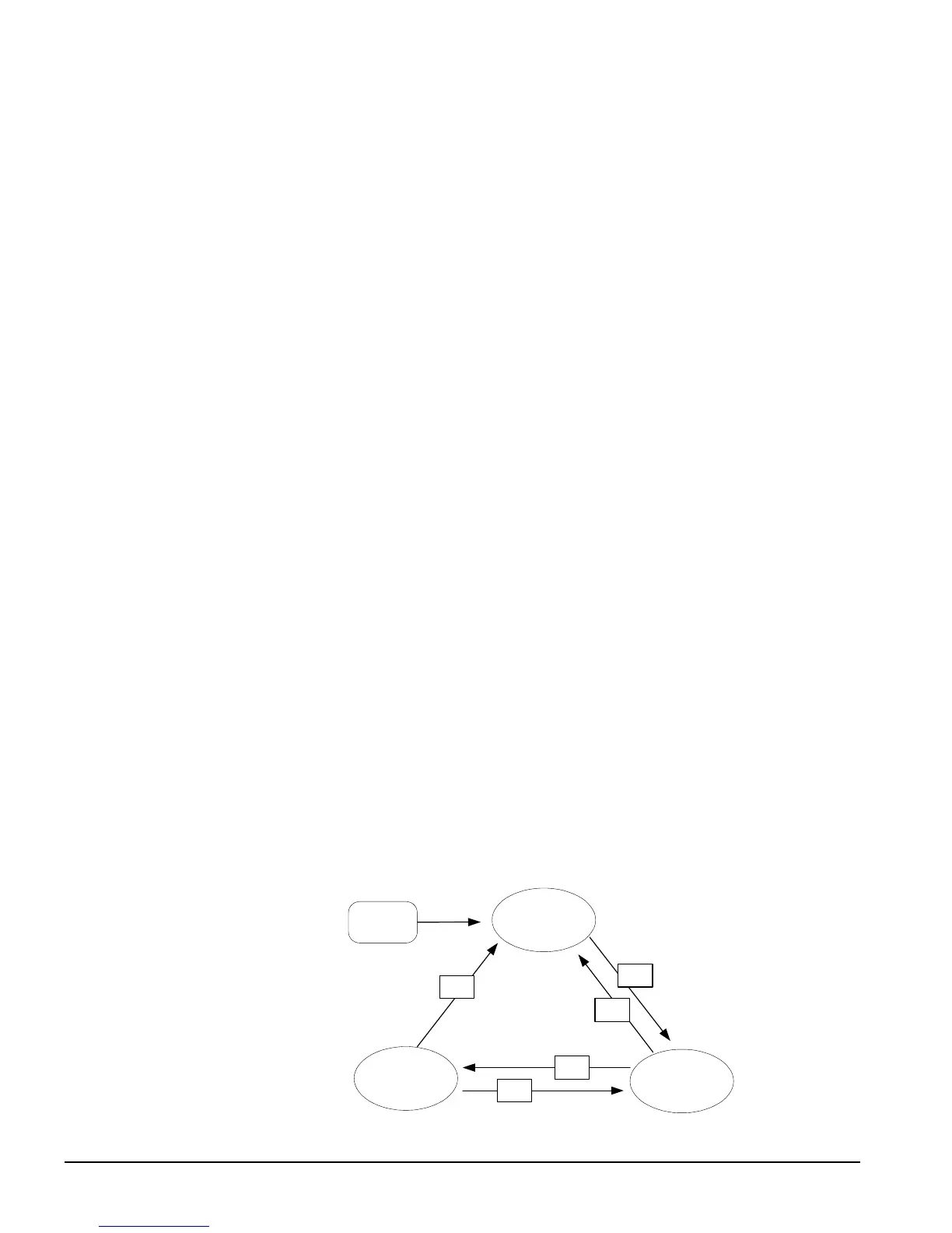
Condenser Water Pump State Control
If the unit is configured as water-cooled, then the condenser pump is controlled by the state-
transition diagram shown below.
Power ON
OFF
RUN
START
T1
T4
T2
T3
Condenser Pump
States
T5
 Loading...