60 WGS 130A to 190A OM WGS-5
Calibration Procedure:
1. The circuit to be calibrated should be near normal operating temperatures. Note that the
compressor requires sufficient oil pressure to unload the compressor while it is running,
and may load up due to lack of oil feed pressure.
2. On the Circuit controller, first verify what your current slide target is at screen “View
Circ Status (1)” and then go to screen “SET COMP SPs (2)” to switch circuit into
manual slide control. Note: Some hold limits will be ignored but all alarm limits are
still active while in manual slide control.
3. Slowly take the circuit to 0% slide position. When the slide target is at 0%, verify that
the unload coil is energized.
4. Find the slide indicator device located on the left side of the compressor facing the
discharge end. Unscrew the metal cap and press the calibrate button beside the LED.
The red LED will come on for about 30 seconds and then start to blink. The indicator is
now calibrated at 0%.
5. Now, slowly take the circuit to 100% slide position, watching that the suction pressure
and other unit readings are OK. Always keep discharge superheat above 22°F. When
the slide target is at 100%, verify that the load coil is energized. Press the calibrate
button. The red LED will come on for about 30 seconds and then the green LED will
come on. The indicator is now calibrated at 100%.
6. The mechanical calibration is now complete for the compressor you are working with.
Replace the calibration cap.
7. Once you have the mechanical slide calibration complete you may fine tune the
calibration from the circuit controller, if necessary. On the circuit controller scroll all
the way to the right, this is the calibration and offsets menu. Scroll down until you see
“SET SENSOR OFFSET(3)”. You will see an adjustment for Min Load and Max Load
and on the bottom line you will see the value of actual slide position indicator. Add
offset until value is within +/-.5% of the corresponding full load or minimum load
position.
8. Repeat calibration procedure until all circuits have min and max positions calibrated.
Note: The Slide Indicator Transducers may vary a considerable amount with
temperature change, and therefore they need to be calibrated at typical running
temperatures.
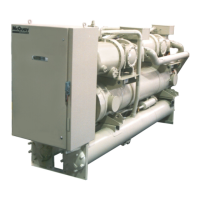
Figure 9, Slide Indicator and Coils
Load Coil
Unload Coil
Slide Indicator
 Loading...